Microcontroller projects
Logic-level shifter tips and tricks
last updated: 2021-07-02
Intro
A cool bidirectional logic-level shifter circuit is all over the internet. It is often used for serial or I²C interfaces. Here a version to connect a 3.3 V data line (ESP, Pico) to a 5 V device.
But lately I run in some problems by using this circuit with NeoPixel LED's. So I had to take a closer look.
Beware of the frequency!
The mentioned interfaces run at about 100 kHz. But modern I²C interfaces use often 400 kHz. Even at 100 kHz the signal is not optimal. At 400 kHz the circuit does not work any more (right image).
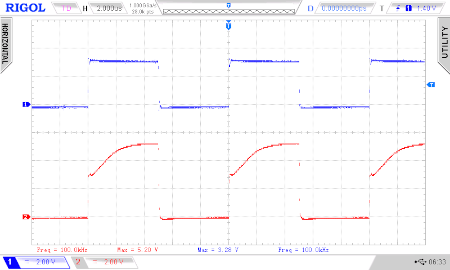
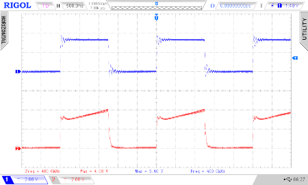
By looking at a logic-level shifter breakout board, I realised that they used the same circuit with 10 kΩ resistances:
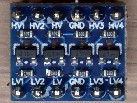
So the measuring results are the same for this board.
Use 1 kΩ instead of 10 kΩ!
So a let's raise the current by using 1 kΩ resistances instead of 10 kΩ:
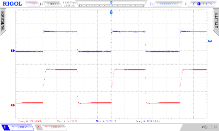
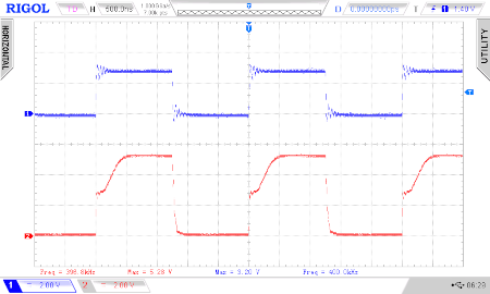
So that's a little better. But the NeoPixel work with 800 kHz. Here the screens for 800 kHz and 2 MHz:
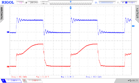
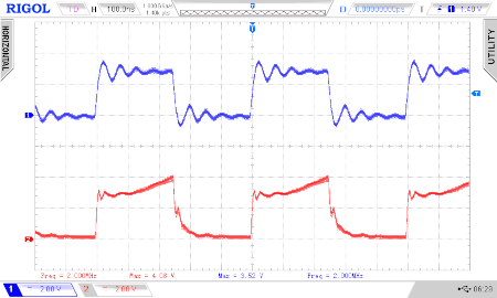
Use 74HCT125 for NeoPixel!
To get NeoPixel work with an ESP, we don't need a bidirectional logic-level shifter, an unipolar logic-level shifter suffices.
5 V NeoPixel need more than 4,3 V on the data line to work faultlessly, so we can use the 74HCT125 IC for our NeoPixel! The 74HCT125 has 4 bus buffer gates with high-current outputs and a low power consumption.
And it works up to 1 MHz.
We connect 5 V to pin 14 and GND to pin 7 as for most ICs of the 74xxx family. The Enable pins of the gates must be connected with GND. Here a circuit from my neoclock2 using this chip:
Interesting links
