Microcontroller projects
ESP8266 and ESP32 Programmer
last updated: 30/08/19

To program or flash an ESP chip it needs to be placed in a mode where it will accept the new incoming program. This is done with a reboot (RESET or EN (Enable) pin to low (active low) and then high again) and simultaneously holding the GPIO0 pin to low. GPIO0 is high in normal mode, so best is to tie it with a pull-up resistor to VCC to avoid the boot mode.
The program itself is send over serial (TIA-232).
| RESET | GPIO0 | mode |
|---|---|---|
1 |
1 |
normal |
1→0→1 |
0 |
boot |
1→0→1 |
1 |
release to normal |
Some circuits use two buttons to do this manually. We want to use the Arduino IDE and to do it automatically. For this we need two control lines from serial (TIA-232).
TIA-232 (RS-232) control lines DTR and RTS
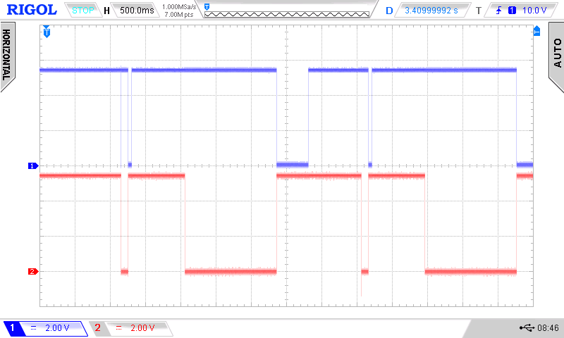
DTR (Data Terminal Ready) and DTR were used in flow control (hardware handshake see tutorial SEN2BUS) for the serial interface. The program esptool.py used to program the ESPs (also in Arduino) activates this lines as shown in the following oscilloscope screen (DTR in blue, RTS in red):

Circuit
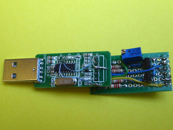
I had a bunch of USB-Serial converter boards from SDS011 fine dust sensors. Fortunately they contain a CH340G chip, witch features DTR on pin 13 and RTS on pin 14 (available on aliexpress). All outputs are 5 V and had to be reduced to 3 V (ESP32 is not 5 V tolerant) with voltage divider (22 kΩ/33 kΩ).
With two BC546B transistors the correct voltages for RESET and GPIO0 can be produced with the following circuit.
As I experienced problems with TxD voltage too low (because of a series resistor on the hacked board), so I used a 22k potentiometer instead of a resistor to be able to adjust the voltage to my needs. Don't forget to cross 'TxD' and 'RxD'.
Programming
In Arduino IDE choose ESP32 Dev Module and set the speed to 115200 bit/s!! Higher speeds often don't work. And don't forget to check for the right port!
Signals
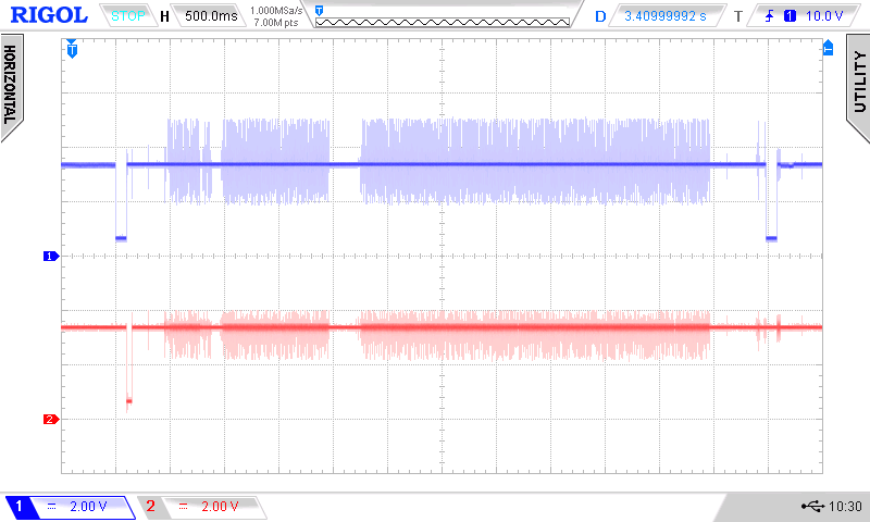
The time diagram shows RESET (EN, blue) and GPIO0 (red) while programming. After the programming is done we get the message:

and see the RESET provoked by RTS on the oscilloscope screen.

