Microcontroller projects
SmartyReader®: Reading encrypted Luxembourgish smartmeter data
last updated: 2026-02-19 (created 2017-08-16)
Quick links
- First some news and infos
- Circuit without PCB
- SmartyReader® V2.2 circuit and PCB
- Arduino Software for the WEMOS D1 mini board
- SmartyReader with ESP32
- SmartyReader with Ethernet
- SmartyReader with LoRa p2p
- SmartyReader with LoRaWAN
- SmartyReader Ethernet P1x5
- Python software to get the data
- Old hardware (V 1.1)
- Downloads
The SmartyReader® gets the data from P1 interface and sends it to your network per WiFi or Ethernet. You can also use LoRa or LoRaWAN.
First some news and infos
SmartyReader® Software Version 1.7
Good to know:
To program the D1 mini pro, remove it from the socket!
If you buy today D1 mini pro's you get often cloned boards. Select in Arduino IDE D1 mini (clone)!
The Ethernet version needs a RESET (button) agter being connected to the Smartmeter to start.Since january first 2025 the costs for the electricity net in Luxembourg include, in addition to the fixed costs, a new calculation that takes power classes into account (3 kW, 7 kW, 12 kW ...). You are assigned to such a power class and have to pay more if your consumption exceeds it. The new software version calculates this data if required. In addition, thanks to Markus Schoellauf, an MQTT discovery method for Home Assistant has been integrated. We also now have a last will :) thanks to Jean-Marie Quintus.
If you don't need Ethernet or LoRa, you can easily build a SmartyReader® without PCB. The only components needed are a resistor (10k) an a capacitor (1000µF). Look in Circuit without PCB.

- The new version for the PCBs
V2.2arrived and the software was adapted. The new PCBs are blue :) and have a header for W5500 Ethernet boards, as the old W5100 Funduino boards are difficult to get hands on.

In Sweden, the P1 port sends clear text strings. Johan Wahlström created a compatible firmware for the SmartyReader®: https://github.com/valis70/hanreader. Thanks Johan :).
Jonas Karlsson was able to integrate the SmartyReader® with esphome (https://esphome.io/components/sensor/dsmr.html) in home-assistant (adjustments to the yaml config). Here is his post on the home assistant community: https://community.home-assistant.io/t/esphome-energy-meter-reading-from-p1-han-port/366457. Thanks Jonas :).
In Austria some provider (e.g. Netz Noe Gmbh) install the same Smartmeter from Sagecom (T210-D) with a different P1 port! The port has no serial connection but M-Bus. The SmartyReader® will not work with these Smartmeter!
All files are now on github: https://github.com/weigu1/SmartyReader.
A new software version adds calculated values, a new config file that let's choose what is published, and support for NTP and BME280. All Infos in the README.md here: https://github.com/weigu1/SmartyReader/tree/main/Arduino/SmartyReader_P1_WiFi_Ethernet.
Housing for the SmartyReader (stl files) on https://github.com/weigu1/SmartyReader/tree/main/FreeCAD.

Basic infos on smarty, encryption and MQTT are here: http://weigu.lu/microcontroller/smartyReader/index.html.
Since my stock of old PCBs is used up, there is a new version without SMD components the SmartyReader V 2.x. A new function in the ESP serial library also makes it possible to invert the serial signal, so that transistors are no longer needed. The new boards have the possibility to use
LoRaorLoRaWAN.Some Smartys were updated by the DSO and deliver now more data (> 1024 Byte) which is a good thing as we get e.g. the power per phase. The old software (before V1.3) will not work any longer if your Smarty was updated, so update your software please to the latest version!
If you want more data, and did not get the upgrade, call your DSO. They can update your Smarty over power-line.
There is a new Basic construction kit. If your are interested in a bare PCB (5 €) or a basic construction kit (Wemos, Jumper and cable included (see picture below) for 25 €, send me a mail. The postal fee (Europe) is 4 € for the kit. I sell these kits to help makers to reduce their energy consumption.


You can use an ESP32 (look at the end of the page) instead of an ESP8266, but I recommend to stay with the ESP8266 as we had more trouble and a higher power consumtion with the ESP32. For an ESP32 it may be necessary do add another big capacitor (e.g. 6800 µF/10 V) to be sure the code starts when powering the SmartyReader® from the Smartmeter. Naturally it is always possible to poer it in parallel per USB.
Sam Grimee has a repo on github with an alternative soft: https://github.com/sgrimee/smarty-reader (Thanks to Sam :)).
Circuit without PCB
I wanted a very small SmartyReader® to fit in the space behind the green Smarty lid. First I tried with a new ESP32-C3 from XIAO, but the software blocked after some minutes. So I stayed with the good old D1 mini pro.

BOM (no PCB)
| 1 | 10 kΩ | reichelt.de: METALL 10,0K |
| 1 | 1000 µF/6,3 V ELKO | reichelt.de: RAD LXZ 6,3/1K0 |
| 1 | WEMOS D1 mini pro | www.wemos.cc |
| 1 | Western cable, 1x connectors, 6-pin | reichelt.de: WK 6-6 2,5M |


SmartyReader® V2.2 circuit and PCB


The new circuits gives us the possibility to add a Lora Chip. The Ethernet (now W5500) and I²C header are still available.

BOM (basic kit)
| 1 | 10 kΩ | reichelt.de: METALL 10,0K |
| 1 or 2 | 100 nF | reichelt.de: Z5U-2,5 100N |
| 1 | 1000 µF/6,3 V ELKO | reichelt.de: RAD LXZ 6,3/1K0 |
| 1 | WEMOS D1 mini pro | www.wemos.cc |
| 1 | RJ12 Jack | reichelt.de: MEBP 6-6S |
| 2 | socket 1x8 straight | reichelt.de: MPE 115-1-008 |
| 1 | PCB | www.weigu.lu |
| 1 | Western cable, 2x connectors, 6-pin | reichelt.de: WK 6-6 2,5M |
The minimum populated board needs the jack, the resistor and the microcontroller. Measures showed that it is good to add C2 (and C1).
My new ammeter currentRanger from LowPowerLab helped to exactly measure the currents and I saw that while WiFi is used, there are many peaks drawing a current from 400 mA up to 800 mA! depending of the board. Even with same boards there could be big differences. An external antenna reduced the current, so I think that not all antennas are well matched. As the peaks are very short, the internal power supply of the smarty (specified up to 250 mA) has no problem to deliver the current, but I guess it is better to add a capacitor to the board. With a 1000 µF capacitor, the spikes come down to 300 mA. The ESP32 and also the new (green) WEMOS have sometimes problems without that capacitor, so add it to the circuit! In the middle of the picture (time axes) the capacitor was added (100 mV correspond to 100 mA)!

The WEMOS (Wemos) is sending the data over WiFi. If your metal control cabinet shields to much the signal, it is possible to connect an external antenna to the WEMOS D1 mini pro by changing a 0 Ω resistor (look here).
If your Wifi is not reliable and you have the possibility to use Ethernet, an W5500 Ethernet board can be added. The PCB is also prepared to connect I2C boards as an RTC with DS3231 or a BME280 to control the temperature. Also other WEMOS shields can be used, e.g. the WEMOS µSD card shield to log the data. If you use everything together, it may be necessary to add an external power source (the Ethernet shield alone already needs the a big part of available 250 mA of the P1 port).


Testing the hardware
If you think the hardware is not working correctly, you can test it with a voltmeter on the RxD pin (µC removed). You can see a change in voltage (3.1 V to 2.5 V) every 10 s (new hardware, or ev. 1 min for older hardware depending on the variable PUBLISH_TIME in the code) by measuring between pin 2 (GND) and pin 7 (RX) on the board header (second and 7th pin on the right side). On one of my voltmeter I don't see it in the displayed numbers but on the bar graph that reacts quicker. This can of course be observed much better with an oscilloscope, where the serial data line changes between 3 V and GND for about 70 ms.
Another possibility is to connect a TTL/USB adapter (RX to RX pin 7 (which is TX from the Smartymeter) and GND to GND (µC removed)), and check the data stream with a terminal program (e.g. cleverterm) with 115200 bit/s (8 data bit, no parity and 1 stop bit).
If you don't see a change there is a possibility that the hardware is not working. To be sure you can measure directly on the P1 cable. Connect pin 2 (Enable) to pin 1 (5 V) and measure between pin 5 (TX) and pin 6 (GND). As the signal is inverted the Voltmeter shows 0 V and reacts every 10 s. To be totally sure use an oscilloscope.
If you get no signal on the cable, test another cable. If there is still no signal, the Smartymeter does not send a signal. Ask your DSO for support.
Arduino Software for the WEMOS D1 mini board
!!NEW!! The software is now on github: https://github.com/weigu1/SmartyReader/tree/main/Arduino/SmartyReader_P1_WiFi_Ethernet.
All explanations to the software are in the README.md file.
The newer software uses my ESPToolbox library, that is included in the sketch folder.
To program the board, you have to take it out of the socket! (RXD prevents proper programming).
The software allows debugging with a blinking LED, over serial (ESP8266: output of the data over Serial1 on Pin D4. For more info see: http://weigu.lu/microcontroller/tips_tricks/esp8266_tips_tricks) and over UDP. Debugging is allowed by the following lines in setup().
    void setup() {
      B.set_led_log(true);                 // use builtin LED for debugging
      B.set_serial_log(true,1);           // 2 parameter = interface (1 = Serial1)
      B.set_udp_log(true, UDP_LOG_PC_IP, UDP_LOG_PORT); // use "nc -kulw 0 6666"
SmartyReader with ESP32
You can use an ESP32 instead of an ESP8266, but I recommend to stay with the ESP8266 as we had more trouble and a higher power consumtion with the ESP32.
The capacitor (1000 µF/10 V is needed because the ESP32 draws a higher current using WiFi for short time slices. It may even be necessary do add another big capacitor (e.g. 6800 µF/10 V) to be sure the code starts when powering the SmartyReader® from the Smartmeter. Naturally it is always possible to power it in parallel per USB.
The MH ET LIVE ESP32MiniKit board is almost pin compatible with the WEMOS (wemos) D1 mini pro. But I had problems to get it work, because there is an error in the pinout sheet on internet. RxD ant TxD are interchanged and not compatible with D1 mini pro!
Fortunately ESP32 has multiplexing features, and so pins can be changed in code. This can be done with the begin command SR_Serial.begin(115200,SERIAL_8N1, 1, 3, true). With this command we define GPIO pin 1 for RxD1 and pin 3 for TxD1. True inverts the stream for newer boards (V2.0).

The capacitor (1000µF/10V, even better 6900µF/10V) is needed because the ESP32 draws a higher current using WiFi for short time slices.
If you want to debug the code over serial, Arduino Serial1 is on SD3 (u1TxD, GPIO10).
The ESPToolbox library detects if an ESP32 or an ESP8266 is used.
SmartyReader with Ethernet
To use Ethernet instead of WiFi a W5500 Ethernet breakout board can be added. In the software (https://github.com/weigu1/SmartyReader/tree/main/Arduino/SmartyReader_P1_WiFi_Ethernet.) you only have to uncomment the #define ETHERNET directive. The overall current with the shield is near the maximum 250 mA that are provided by the P1 port. Normally this works fine, but if you have problems it may be necessary to add an external power source.

The older SmartyReader versions with W5100 Funduino Ethernet board are still supported in the software. Uncomment the #define FUNDUINO_W5100 line.
SmartyReader with LoRa p2p
The new boards (v2.1 and v2.2) can use LoRa instead of WiFi. This is less power consuming with a bigger range. The drawback is that we must reduce the amount of data that we send to stay in the 1 % duty cycle (percentage of time a device is allowed to transmit) of LoRa. For more infos on LoRa look here: http://weigu.lu/tutorials/sensors2bus/09_lorawan/index.html.
When we stay in our internal net we need a LoRa receiver/gateway. This is called LoRa peer to peer. For more infos on LoRa p2p look here: http://weigu.lu/microcontroller/lora_p2p/index.html
On the hardware side we need an SX1276 chip from SEMTECH that can be bought on a breakout board RFM95W-V2.0 from hoperf. We also need two SMD diodes 1N4148 (cathode to GND) and an antenna.
For the chip we have to pay attention because there exist chips in Europe for the 433 MHz and the 868 MHz ISM bands. I normally use the 868 MHz ISM band, because it is less crowded.
Before powering anything, it is mandatory to solder the antenna so the sending chip is not destroyed. We can use a wire of 8.2 cm or an external antenna by soldering an antenna connector (IPEX U.FL SMD). For 433 MHz the wire length is 16.5 cm.

The code is on github. Pay attention to set the publish time so you respect the 1 % duty cycle.
    const long PUBLISH_TIME = 60000;

    // Comment or uncomment the following lines suiting your needs
    #define LORA_P2P        // LORA_P2P
    //#define LORAWAN         // LORAWAN with TTN
SmartyReader with LoRaWAN
When we use LoRaWAN with The Things Network (TTN), we need an internal gateway (available under 80 €) or an external gateway. It would be cool if you install an external gateway to help getting a better coverage of LoRaWAN via TTN in Luxembourg :).
To be able to connecting to the TTN network you need to create an account with TTN and change the variables APPEUI[8], DEVEUI[8] and APPKEY[16] in the sketch. For more infos on LoRa look here: http://weigu.lu/tutorials/sensors2bus/09_lorawan/index.html#link_5.
The code is on github. Pay attention to set the publish time so you respect the 1 % duty cycle.
    const long PUBLISH_TIME = 60000;

    // Comment or uncomment the following lines suiting your needs
    //#define LORA_P2P        // LORA_P2P
    #define LORAWAN         // LORAWAN with TTN

    ...

    // APPEUI and DEVEUI LSB first! APPKEY MSB first!
    static const u1_t PROGMEM APPEUI[8]={ 0x00, 0x00, 0x00, 0x00, 0x00, 0x00, 0x00, 0x00 };
    void os_getArtEui (u1_t* buf) { memcpy_P(buf, APPEUI, 8);}
    static const u1_t PROGMEM DEVEUI[8]={ 0xB4, 0x61, 0x04, 0xD0, 0x7E, 0xD5, 0xB3, 0x70 };
    void os_getDevEui (u1_t* buf) { memcpy_P(buf, DEVEUI, 8);}
    static const u1_t PROGMEM APPKEY[16] = { 0xA1, 0x28, 0xE4, 0x46, 0xBA, 0x02, 0xEF, 0xD4, 0xEC, 0xDA, 0x47, 0xEE, 0x69, 0x1D, 0x15, 0xF9 };
SmartyReader⁵: Ethernet P1x5
A second board with a Teensy 3.6 microcontroller was created to read 5 smartmeter and serial data from my rainwater tank (Teensy 3.6 has 6!! serial ports). Look here for more information
Python software to get the data
This stub is from the old Homepage. It will be updated if time allows it.
A Python (python3) script is used to get our smartmeter MQTT data from the broker. We use the paho.mqtt.client library which can be installed with pip to subscribe to our topic.
sudo pip3 install paho-mqtt
The data is saved in a file (/data) and the old day-files are archieved (/data_archive). The script also generates a png-file with gnuplot that is displayed on an internal homepage and sent to an email address (full code in Downloads).
To to so we can use the same raspberry pi witch holds the broker.
MQTT client
You have to adjust possibly the broker IP address and your smartmeter id (these are the last 3 digits of your smarty id (ex: "345" for SAG1030700012345) ).
    #!/usr/bin/python3
    #
    # Name:         smartyreader.py
    # Purpose:      Client to get MQTT data from Mosquitto
    # Author:       weigu.lu
    # Date:         8/17
    #
    ...
    import paho.mqtt.client as mqtt
    ...
    clientID   = "getsmarty_p1"
    brokerIP   = "192.168.178.101"
    brokerPort = 1883
    topic      = "basement/smarty1"
    sm_id      = "345"

    # Callback that is executed when the client receives a CONNACK response from the server.
    def onConnect(client, userdata, flags, rc):
       print("Connected with result code " + str(rc))
       mqttc.subscribe(topic, 0)  # Subscribe to the topics (topic name, QoS)

    # Callback that is executed when we disconnect from the broker.
    def onDisconnect(client, userdata, message):
       print("Disconnected from the broker.")

    # Callback that is executed when subscribing to a topic
    def onSubscribe(client, userdata, mid, granted_qos):
       print('Subscribed on topic.')

    # Callback that is executed when unsubscribing to a topic
    def onUnsubscribe(client, userdata, mid, granted_qos):
       print('Unsubscribed on topic.')

    # Callback that is executed when a message is received.
    def onMessage(client, userdata, message):
        # Subscribing in on_connect() means that if we lose the connection and
        # reconnect then subscriptions will be renewed.
        global sm, smp, sme, sm_mn #p power, e energy, mn at midnight
        now = datetime.now()
        now_time = now.time()
        if now_time >= time(23,59,00) and now_time <= time(23,59,59):
            sm_mn=ioj["c1"].rstrip("*kWh") # change to "p1" for production
        ftime = strftime("%Y_%m_%d", localtime())
        ftime3 = strftime("%d.%m.%y %H:%M:%S", localtime())
        io=message.payload.decode("utf-8");
        try:
            ioj=json.loads(io)
        except:
            ioj={"dt":"error"}
        print(ioj)
        temp = ioj["dt"]
        if (temp[0]!='e') and (temp[0]!='c'):
            sm_new=ioj["c1"].rstrip("*kWh") # change to "p1" for production
            if sm!="0":
                smp = str(round((float(sm_new)-float(sm))*60000.0,3))
            sm=sm_new
            sme=str(float(sm)-float(sm_mn))
            if sme[0]=='-':
                sme="0"
            try:
                f = open (sm_p1_datafile1, 'r')
            except IOError:
                print("error reading file "+sm_p1_datafile1)
            lineList = f.readlines()            #read all lines
            f.close()
            try:
                f = open (sm_p1_datafile1, 'a')
            except IOError:
                print ("Cannot create or find file: " + sm_p1_datafile1)
            try:
                f2 = open (sm_p1_datafile2+ftime+'.min', 'a')
            except IOError:
                print ("Cannot create or find file: " + sm_p1_datafile2)
            if (len(lineList)) == 1:
                sm_p1_data = ' '.join((ftime3,sm,sme,smp))
                sm_p1_data = sm_p1_data + '\n'
            else:
                line = lineList[len(lineList)-1]    #get the last line
                lline =shlex.split(line)            #convert string (space seperated items) to list
                sm_p1_data = ' '.join((ftime3,sm,sme,smp))
                sm_p1_data = sm_p1_data + '\n'
            print (sm_p1_data,end='')
            f.write(sm_p1_data)
            f2.write(sm_p1_data)
            f.close()
            f2.close()
        else:
            print("loop not executed (error or connect message)")

    ...
    # Main
    mqttc = mqtt.Client(client_id=clientID, clean_session=True) # create client
    mqttc.on_connect      = onConnect   # define the callback functions
    mqttc.on_disconnect   = onDisconnect
    mqttc.on_subscribe    = onSubscribe
    mqttc.on_unsubscribe  = onUnsubscribe
    mqttc.on_message      = onMessage
    mqttc.connect(brokerIP, brokerPort, keepalive=60, bind_address="") # connect to broker
    mqttc.loop_start() # start loop to process callbacks! (new thread!)

    sm ="0"
    smp = "0"
    sme = "0"
    sm_mn = "0"

    try:
        while True:
            now = datetime.now()
            now_time = now.time()
            ...

    except KeyboardInterrupt:
        print("Keyboard interrupt by user")
        mqttc.loop_stop() # clean up
        mqttc.disconnect()
Internal homepage with daily graphic
Static IP address
To access the raspberry pi we will set a static IP address.
Use the editor nano to append the following to the file /etc/dhcpcd.conf.
    # Custom static IP address for eth0.
    interface eth0
    static ip_address=192.168.1.67
    static routers=192.168.1.1
    static domain_name_servers=192.168.1.1 8.8.8.8

    # Custom static IP address for wlan0.
    interface wlan0
    static ip_address=192.168.1.69
    static routers=192.168.1.1
    static domain_name_servers=192.168.1.1 8.8.8.8
    cd /etc
    sudo nano dhcpcd.conf
Save with CTRL+O and exit with CTRL+X.
Setting up the webserver Lighttpd on the raspi
Lighttpd is an efficient high performance web server. It has a small memory footprint and an effective management of the cpu-load compared to other web-servers. Naturally you can use another web server, but possibly you have to adjust the path to your web page.
    sudo apt update
    sudo apt upgrade
    sudo apt install lighttpd
Test if the web server is running by typing the ip address of your raspi in the url field of your browser.
The html files are in in /var/www/html. Copy the following html code (filename: index.html) to /var/www/html:
    <!DOCTYPE html>
    <head>
      <title>Smarty P1</title>
    </head>
    <body>
    <h1>Smarty Data</h1>
    <p><img src="png/sm_p1_daily.png" alt="smarty data"></p>
    </body>
    </html>
Also create an empty directory named /png in /var/www/html.
sudo mkdir /var/www/html/png
Using gnuplot for graphics
sudo apt install gnuplot
To test gnuplot you can use the following command:
    cd /home/pi/smarty/gp
    gnuplot sm_p1.gp
The sm_p1.gp is created by our Python script from a template file. This template file is found in /smarty/gp (it is contained in the file smartyreader.zip). Here is the code that generates the gp file:
    def sm_create_gp_file():
        """ The function prepares the gp file for plotting with gnuplot. First the
        old gp file is deleted. Then it uses the xx_gp_template.gp file in
        ~/../gp and replaces the keywords between the % sign by creating
        a new gp (xx.gp) file."""
        ftime2 = strftime("%d.%m.%y", localtime())
        Title = ftime2
        XFormat = '"%H:%M"'
        XTics = "60*60" #seconds
        Begin = ftime2 +" 00:00:01"
        End = ftime2 +" 23:59:59"
        Output = png_dir + "sm_p1_" + ftime + ".png"
        Input = sm_p1_datafile1
        try:
            os.remove(sm_p1_gnupfile2)
        except OSError:
            pass
        try:
            gf1 = open (sm_p1_gnupfile1,'r')
        except IOError:
            print ("Cannot find file: " + sm_p1_gnupfile1)
        try:
            gf2 = open (sm_p1_gnupfile2,'a')
        except IOError:
            print ("Cannot find file: " + sm_p1_gnupfile2)
        gline1 = gf1.readline()
        while gline1 != "":
            if "%TITLE%" in gline1:
                gline1 = gline1.replace("%TITLE%",Title)
            if "%XFORMAT%" in gline1:
                gline1 = gline1.replace("%XFORMAT%",XFormat)
            if "%XTICS%" in gline1:
                gline1 = gline1.replace("%XTICS%",XTics)
            if "%BEGIN%" in gline1:
                gline1 = gline1.replace("%BEGIN%",Begin)
            if "%END%" in gline1:
                gline1 = gline1.replace("%END%",End)
            if "%OUTPUT%" in gline1:
                gline1 = gline1.replace("%OUTPUT%",Output)
            if "%INPUT%" in gline1:
                gline1 = gline1.replace("%INPUT%",Input)
            gf2.write(gline1)
            gline1 = gf1.readline()
        gf1.close()
        gf2.close()
Here the result with gnuplot:

Sending mails
First you have to install ssmtp:
    sudo apt-get install ssmtp      # needed
    sudo apt-get install mailutils  # not mandatory
    sudo apt-get install mpack      # for attachments
With your editor, set up the defaults for SSMTP in /etc/ssmtp/ssmtp.conf. Edit the fields:
    root=my@mail.adr
    mailhub=smtp.xxx.xx:587
    hostname=localhost
    rewriteDomain=www.xxx.com
    FromLineOverride=YES
    AuthUser=youruserid
    AuthPass=xxxxxxxxxxxx
    UseSTARTTLS=YES
Test your mail with:
echo "Hello world email body" | mail -s "Test Subject" my@mail.adr
The Python script will send the daily graphic per mail at 1 pm in the morning.
Start your script automatically with cron
If you want to start the Python script automatically at reboot, add the following line to your /etc/crontab file.
@reboot root python3 /home/pi/smarty/smartyreader.py >> /home/pi/smarty/smartyreader_log.txt 2>&1
The output of the Python script is redirected to a text-file, for debugging. To log the cron jobs uncomment cron in the file /etc/rsyslog.conf. You will find the log file in /var/log/cron.log.
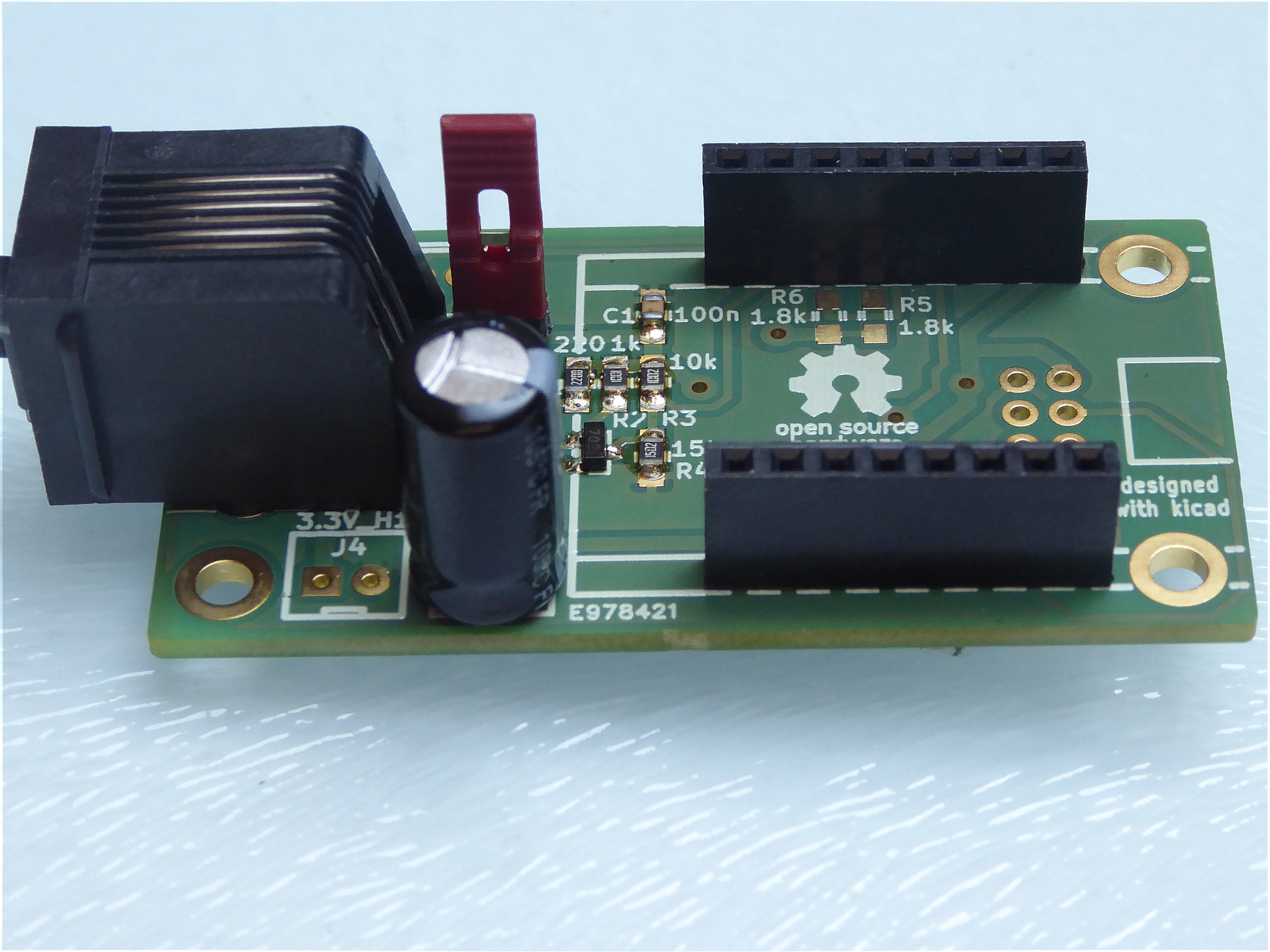
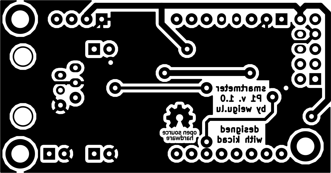
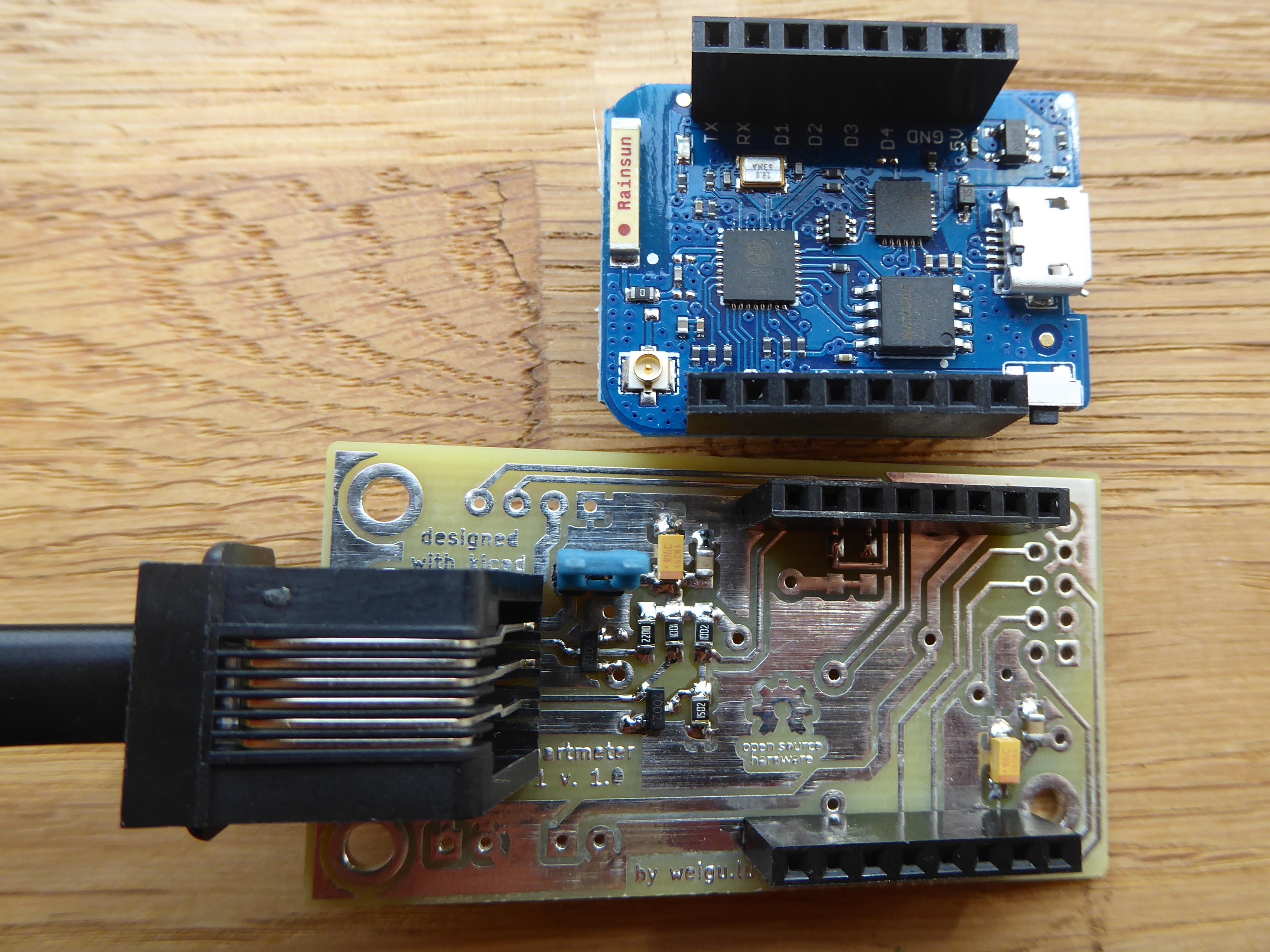
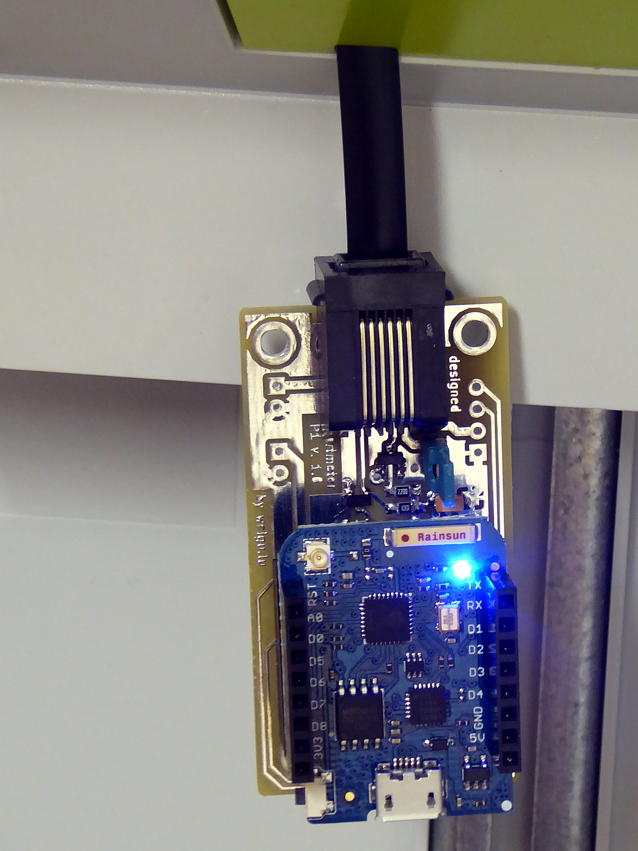
Old hardware (V 1.1)
- To get data, the data request line (pin 2) has to be high (5 V). As we use a microcontroller working on 3.3 V we need a transistor to bring the voltage of the data request line to 5 V (Q1). The transistor inverts the logic!, so a
LOWinitiates the data communication! - Data pin 5 sends an inverted serial signal (EIA232) with 8N1. This line is open collector! so we need a resistor to 5 V if we want to see a signal.
- The second transistor (Q2) inverts the serial data to be EIA232 compliant and a voltage divider (R3, R4) brings the voltage down to 3.3 V.
More details in the Dutch Smart Meter Requirements.
The statement: For backward compatibility reason, no OSM is allowed to set “Data Request” line low (set it to GND or 0V).
is not relevant for the Luxembourgish smartmeter, because an optocoupler diode gets the signal.

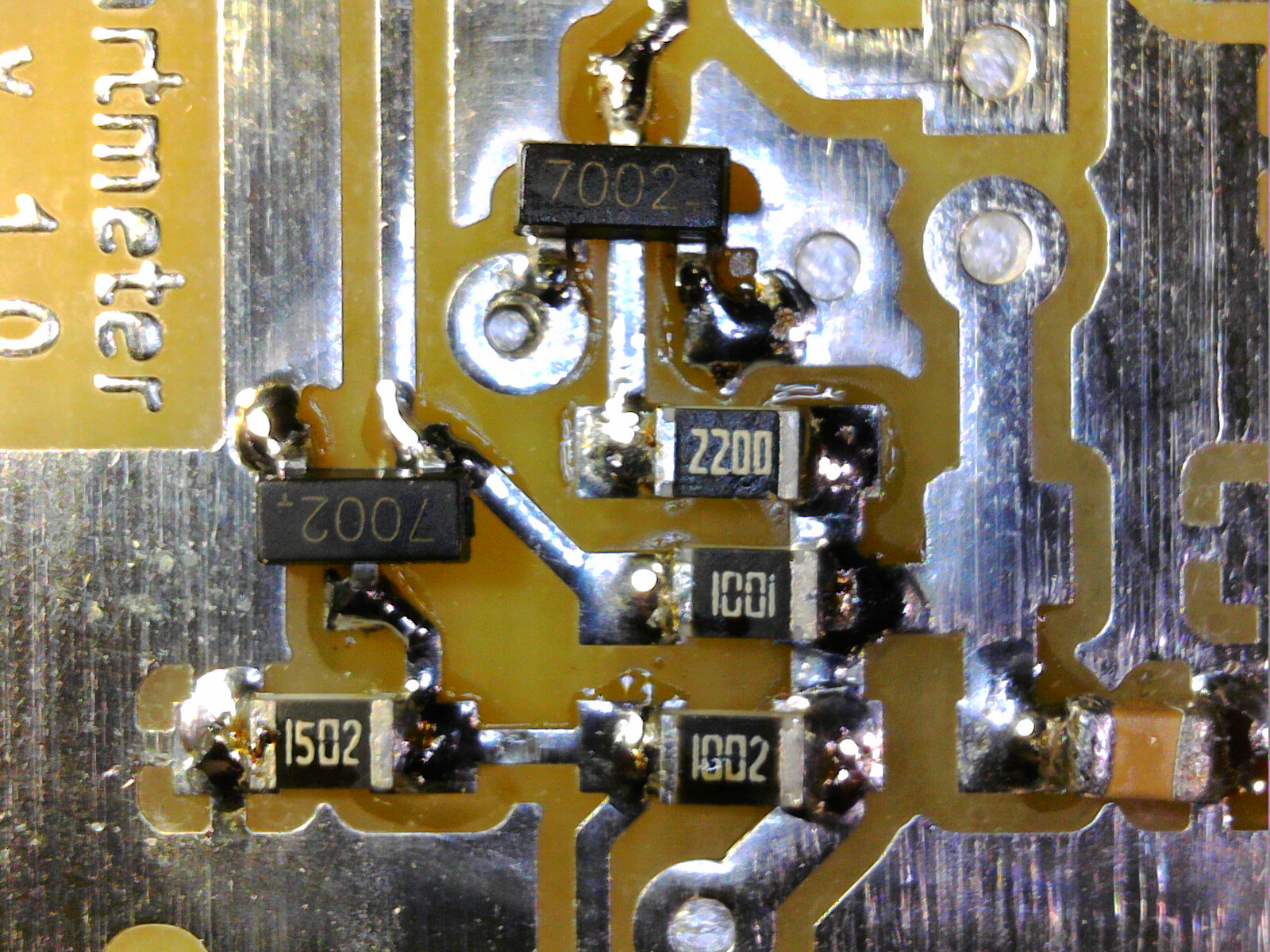
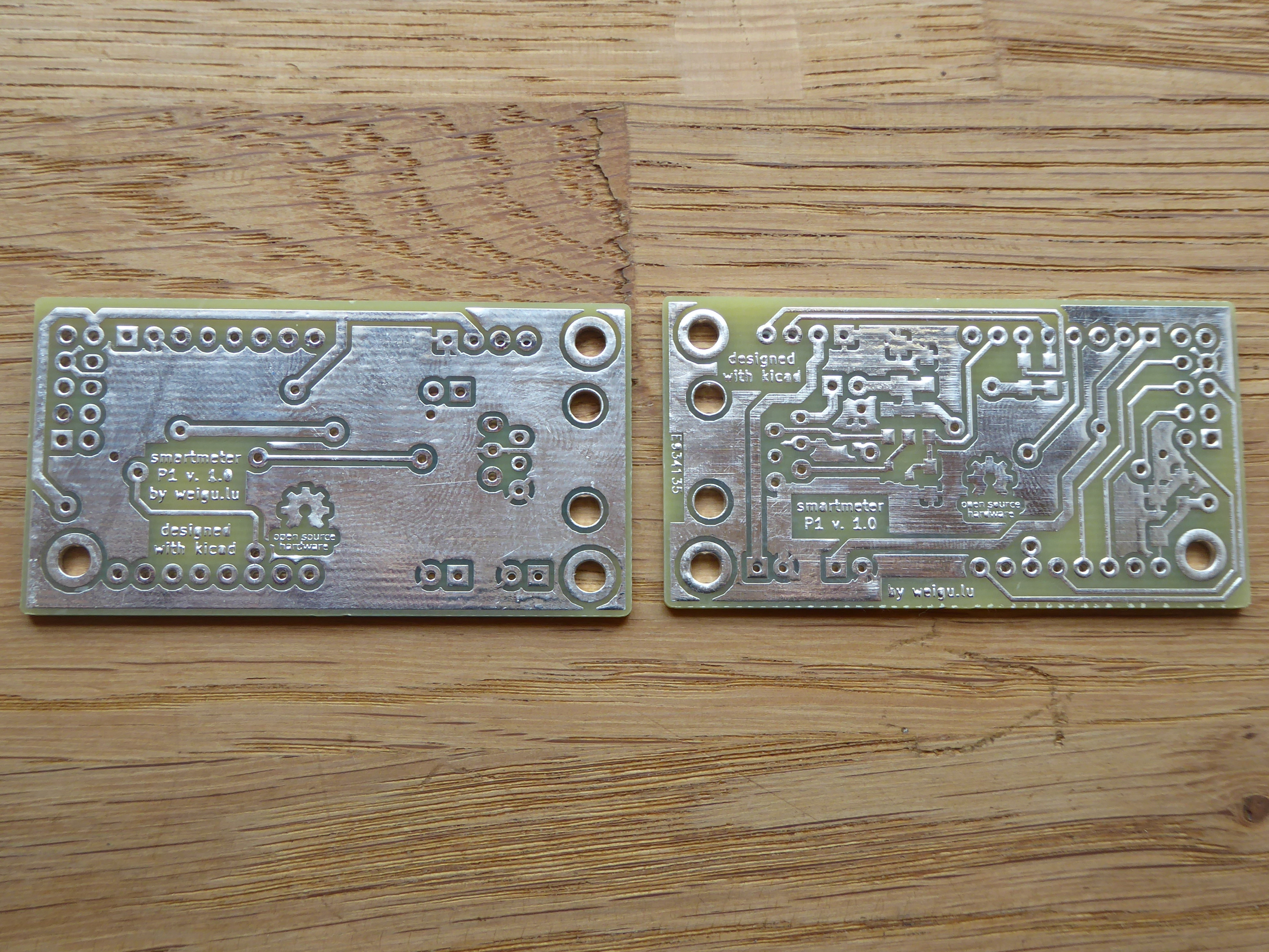
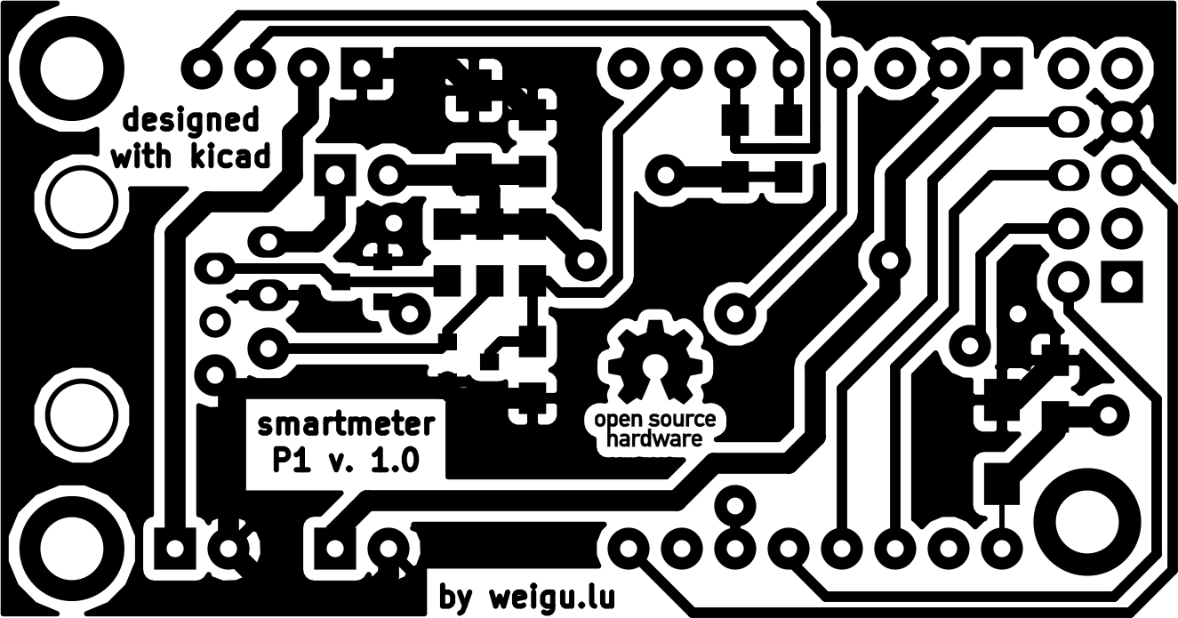
Circuit and PCB

BOM (basic kit)
| 1 | 220 SMD 0805 | reichelt.de: RND 0805 1 220 |
| 1 | 1k Ω SMD 0805 | reichelt.de: RND 0805 1 1,0K |
| 1 | 10k Ω SMD 0805 | reichelt.de: RND 0805 1 10K |
| 1 | 15k Ω SMD 0805 | reichelt.de: RND 0805 1 15K |
| 1 | 100 nF SMD 0805 | reichelt.de: X7R 0805 CF 100N |
| 1 | 1000 µF/6,3 V ELKO | reichelt.de: RAD LXZ 6,3/1K0 |
| 2 | 2N7002 SOT-23 | reichelt.de : 2N 7002 SMD |
| 1 | WEMOS D1 mini pro | www.wemos.cc |
| 1 | RJ12 Jack | reichelt.de: MEBP 6-6S |
| 2 | socket 1x8 straight | reichelt.de: MPE 115-1-008 |
| 1 | pin header | reichelt.de: MPE 087-1-002 |
| 1 | jumper | reichelt.de: JUMPER 2,54GL SW |
| 1 | PCB | www.weigu.lu |
| 1 | Western cable, 2x connectors, 6-pin | reichelt.de: WK 6-6 2,5M |
The WEMOS (Wemos) is sending the data over WiFi. If your metal control cabinet shields to much the signal, it is possible to connect an external antenna to the WEMOS D1 mini pro by changing a 0 Ω resistor (look here).
If your Wifi is not reliable and you have the possibility to use ethernet, an W5100 Funduino ethernet board can be added. The PCB is also prepared to use an RTC with DS3231 and an WEMOS µSD card shield to log the data.
In the second version of the board I omitted the 100 µF capacitors, because the boards all worked fine without the capacitor. My new ammeter currentRanger from LowPowerLab helped to exactly measure the currents and I saw that while WiFi is used, there are many peaks drawing a current from 400 mA up to 800 mA! depending of the board. Even with same boards there could be big differences. An external antenna reduced the current, so I think that not all antennas are well matched. As the peaks are very short, the internal power supply of the smarty (specified up to 250 mA) has no problem to deliver the current, but I guess it is better to add a capacitor to the board. With a 1000 µF capacitor, the spikes come down to 300 mA. The ESP32 and also the new (green) WEMOS have sometimes problems without that capacitor, so add it to the circuit! In the middle of the picture (time axes) the capacitor was added (100 mV correspond to 100 mA)!
Downloads
- !!NEW!! Software on github: https://github.com/weigu1/SmartyReader
- Python code and directory structure (unzip to your home directory (/home/pi))
- Gnuplot template file
