Microcontroller projects
last updated: 2021-04-17
Pico-HAT: Connect your Raspi with the Pico through I²C
Introduction
My Mechanical Ventilation Heat Recovery (MVHR) system PIVENTI runs on a Raspi with attached Teensy 2.0 board. As the Raspi has not enough Serial interfaces I chose I²C for the communication, and this is running very well.
A next step will be the renewing of my heating control. And here I want to try the new Raspi Pico with RP2040 µC.
The Pico connects to all the sensors and actuators and can act in Real Time. The Raspi can do the rest (Wifi, Webserver, MQTT, Display ...). The Pico is an I²C slave to the Raspi and the Raspi sends commands with a Python script to the Pico. An Arduino program on the Pico answers with sensor data or by switching an actuator.
As the Arduino IDE runs on a Raspi, both device (Raspi and Pico) can be reprogrammed via VNC from any computer, and I find this pretty amazing :).
To be flexible I and to enhance my KiCAD skills I designed a HAT (Hardware Attached on Top) with multiple headers to connect the sensors and actuators.
The Pico-HAT
Features
The Raspi is connected through I²C with the Pico. Serial is prepared if needed (by adding 2 0 Ω resistors).
The Pico can be powered over USB (recommended if you want to reprogram it via Arduino IDE and VNC) or through the Raspi (5 V).
All GPIOs have the possibility to add a voltage divider to reduce the input voltage (e.g. 5 V to 3.3 V), or to add an external pull-down resistor.
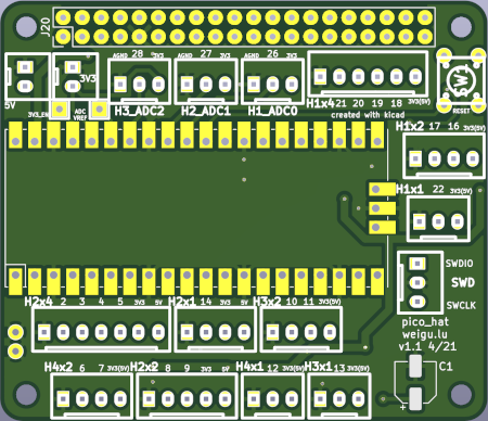
All headers have beneath a ground pin, one or two power pins (3.3 V or 5 V;
H2headers: 3.3 V and 5 V).Additionally we get a RESET-button, an
SWDheader, 2 power header (3.3 V and 5 V), 2 Ground pins, an an 3V3_EN and ADC_VREF pins.
Circuit
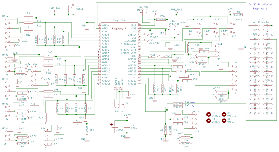
The circuit is designed with KiCAD. The HAT is open hardware and can be downloaded here.
PCB
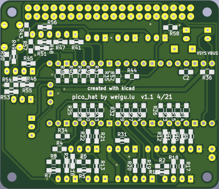
The PCBs arrived :).
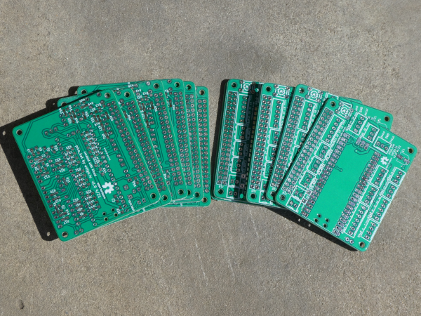
The PCB needs only the Pico, and the Raspi header and if desired the two capacitors (C1 220µF and C2 100nF) and the RESET button. And naturally the headers you need. All headers are 2.54 mm. You can use Dupont headers, but Molex headers are better suited because they prevent polarity reversal. You can also use JST-connectors if you don't populate all the headers (they may be a little to wide).
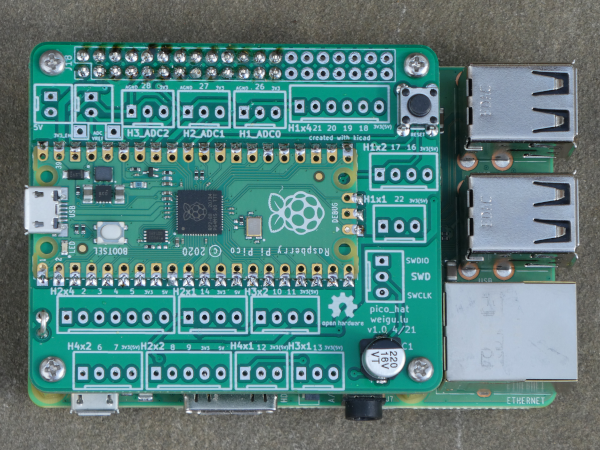
The headers
| Name | Pin 1 | Pin 2 | Pin 3 | Pin 5 | Pin 5 | Pin 6 | Pin 7 |
|---|---|---|---|---|---|---|---|
5V_Pico |
GND | 5 V | |||||
3V3_Pico |
GND | 3.3 V | |||||
SWD |
SWDIO | GND | SWCLK | ||||
H1_ADC0 |
GND | ADC0 (GPIO26) | 3.3 V | ||||
H2_ADC1 |
GND | ADC1 (GPIO27) | 3.3 V | ||||
H3_ADC2 |
GND | ADC2 (GPIO28) | 3.3 V | ||||
H1x1 |
GND | GPIO22 | 3.3 V (or 5 V) | ||||
H3x1 |
GND | GPIO13 | 3.3 V (or 5 V) | ||||
H4x1 |
GND | GPIO12 | 3.3 V (or 5 V) | ||||
H2x1 |
GND | GPIO12 | 3.3 V | 5 V | |||
H1x2 |
GND |
GPIO17 (alt. RX0-TX_Raspi) |
GPIO16 (alt. TX0-RX_Raspi) |
3.3 V (or 5 V) |
|||
H3x2 |
GND | GPIO10 | GPIO11 | 3.3 V (or 5 V) | |||
H4x2 |
GND | GPIO6 | GPIO7 | 3.3 V (or 5 V) | |||
H2x2 |
GND | GPIO8 | GPIO9 | 3.3 V | 5 V | ||
H1x4 |
GND | GPIO21 | GPIO20 | GPIO19 | GPIO18 | 3.3 V (or 5 V) | |
H2x4 |
GND | GPIO2 | GPIO3 | GPIO4 | GPIO5 | 3.3 V | 5 V |
Changing from 3.3 V to 5 V and adding a voltage divider to get a 5 V input
- Changing from 3.3 V to 5 V:
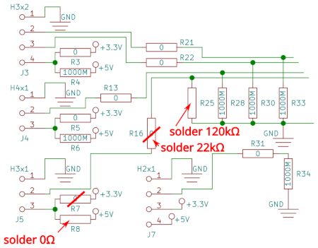
With a cutter cut the connection to 3.3 V inside the SMD pad, and solder a 0 Ω SMD resistor (0805) to 5 V. As an example we will do this for the HeaderH3x1. The circuit tells us, that we need to cutR7and solder an 0 Ω resistor toR8.
- Adding a voltage divider to get a 5 V input:
With the same headerH3x1we have to cutR16and solder two resistors. We choose 22 kΩ forR16and 39 kΩ forR25.
This gives us 5 V*39 kΩ/(22+39) kΩ = 3.2 V.
STOP! That is the theory. When measuring my voltage, I got only 2 V!!
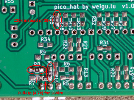
So I measured the input current of the Pico pin and it took 56 µA! I expected 1 µA but there seems to be an internal pull-down with about 60 kΩ. So we have to rise the resistance to 120 kΩ, to get an overall resistance R25//RPD (120k//60k) = 40k.
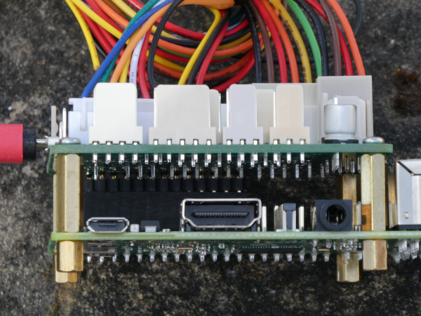
In the following image we see the changes. I also added a pull-up resistor (GPIO13-5 V), because I need the header for a 1-Wire bus.
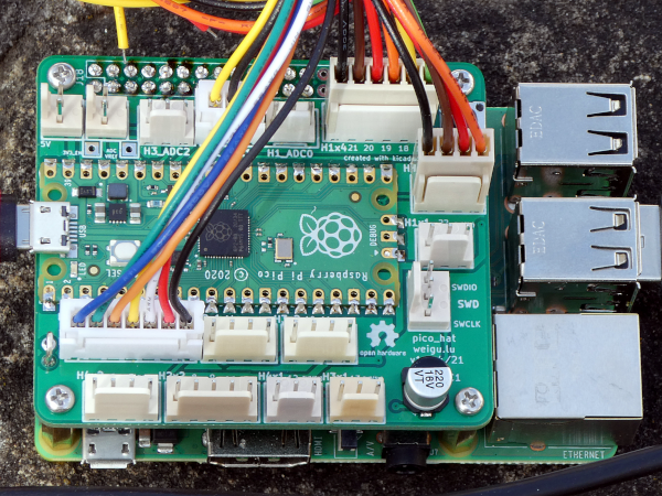
After soldering the headers the HAT can be mounted to the Raspi:
The Pico-HAT Software
As stated both devices use I²C (TWI) interface. More infos about I²C can be found in my tutorials here, or in German here or here (pdf).
Three years ago while using the Teensy 2.0 as slave with a Raspi I ran in some problems, but unfortunately didn't document them, so this time again I needed some time to get everything running, but this time I will document the problem :). Look at the end of the page! In short we need a write + read command in Python instead of only a read command to get it work.
Python program for the Raspi as I²C master
This test program sends the 3 bytes to the Pico, defining how often the onboard LED will blink and defining the delay time in ms between the toggling (command 0x0A). It reads 2x2 bytes from the Arduino (temperature (0x81) and humidity (0x82).
#!/usr/bin/env python3
# -*- coding: utf-8 -*-
    ''' pico_hat_i2c.py  weigu.lu
        Raspberry Pi is Master, Pico is slave
        This test program sends the 3 bytes to the Pico, defining how often
        the onboard LED will blink and defining the delay time in ms between
        the toggling (command 0x0A).
        It reads 2x2 bytes from the Arduino (temperature (0x81) and humitity (0x82)
        More infos on weigu.lu '''

    import smbus

    PORT = 1 # (0 for rev.1, 1 for rev 2!)
    I2C = smbus.SMBus(PORT)
    PICO_I2C_ADDRESS = 0x20

    COMMAND_TEMP1 = 0x81  # MSB = 1 for read
    COMMAND_HUM1 = 0x82
    COMMAND_BLINK = 0x0A  # MSB = 0 for write
    BLINK_RATE = 10       # how many times to blink (1 byte)
    BLINK_DELAY = 50      # delay between toggling im ms (1 word)

    def get_sensor_data(command):
        ''' write command and read data (1 word)'''
        I2C.write_byte(PICO_I2C_ADDRESS, command)
        return I2C.read_word_data(PICO_I2C_ADDRESS, command)/100.0

    def set_blink(blink_command, blink_rate, blink_delay):
        ''' write to Pico: blink rate (1 byte) and delay (2 byte)'''
        blink = [] # list for 3 bytes
        blink.append(blink_rate)
        blink.append(blink_delay//256)
        blink.append(blink_delay%256)
        I2C.write_i2c_block_data(PICO_I2C_ADDRESS, blink_command, blink)

    # main: try the commands
    print("Temperature 1: ", get_sensor_data(COMMAND_TEMP1), "°C")
    print("Humidity 1:    ", get_sensor_data(COMMAND_HUM1), "%")
    set_blink(COMMAND_BLINK, BLINK_RATE, BLINK_DELAY)
Arduino program: Pico as I²C slave
The Arduino core for the Pico is in an early state, but everything runs. Thanks to Earle F. Philhower, III :). All infos can be found on his Github page: https://github.com/earlephilhower/arduino-pico.
I had no chance with the official Raspberry Pi Pico support that was added to Arduino IDE some days ago. I got an error while uploading.
The Pico is connected through USB with one port of the Raspi. It is important to press the Pico boot button before and while connecting to the Raspi with the USB cable.
Close the serial monitor before uploading a sketch (reopen afterwards). In the file-manager you can switch off the pop-up menu showing options for an inserted removable media (Filemanager -> Edit -> Preferences -> Volume Management -> Show available options...).
As I got often errors while uploading, I soldered two 0 Ω Resistors to R43 and R44 and so connected the Pico Serial to the Raspi Serial. On the Raspi I installed cutecom as serial monitor.
sudo apt install cutecom
Now I can send my debug infos to ttyS0 (enable serial in Preferences -> Raspberry Pi Configuration).
If you want to do this, add the following lines to the code (setup) and replace Serial. with Serial1. ().
  Serial1.setRX(17);
  Serial1.setTX(16);
  Serial1.begin(115200);
Now here the Arduino Sketch:
    /* pico_hat_i2c.ino   weigu.lu
     * Raspberry Pi is Master, Pico is slave
     * The Raspi program sends 3 bytes to the Pico, defining how often
     * the onboard LED will blink and defining the delay time in ms between
     * the toggling (command 0x0A).
     * The pico responds with 2x2 bytes (temperature and humidity) when receiving
     * the commands 0x81 and 0x82.
     * More infos on weigu.lu
     */

    #include <Wire.h>

    //#define DEBUG      // uncomment if more infos needed in serial monitor

    const byte PICO_I2C_ADDRESS = 0x20;
    const byte LED_PIN = LED_BUILTIN;   // LED_BUILTIN or other pin
    bool LED_LOGIC = 1;                 // positive logic: 1, negative logic: 0
    const unsigned long DELAY_MS = 3000;
    const unsigned long LED_BLINK_DELAY_MS = 100;

    struct {
      float volatile t1; // temperature
      float volatile h1; // humidity
    } tx_data;

    struct {
      byte volatile blink_nr = 3;
      word volatile blink_delay = 100;
    } rx_data;

    byte volatile command = 0;
    byte volatile rx_flag = 0;
    byte volatile tx_flag = 0;
    const byte tx_table_bytes = 20;
    byte volatile tx_table[tx_table_bytes]; // prepare data for sending over I2C

    void setup() {
      Serial.begin(115200);             // for debugging
      init_led();
      Wire.begin(PICO_I2C_ADDRESS);     // join i2c bus
      Wire.onReceive(i2c_receive);      // i2c interrupt receive
      Wire.onRequest(i2c_transmit);     // i2c interrupt send
      tx_data.t1 = 21.30;               // simulate a temperature
      tx_data.h1 = 60;                  // simulate humidity value
    }

    void loop() {
      blink_led_x_times(rx_data.blink_nr,rx_data.blink_delay);
      #ifdef DEBUG
        if (rx_flag) {
          Serial.println("RX with " + String(rx_flag) + "byte; command: " + String(command));
          rx_flag = 0;
        }
        if (tx_flag) {
          print_tx_table();
          tx_flag = 0;
        }
      #else
        delay(3000);
      #endif
    }

    void i2c_receive(int bytes_count) { // bytes_count gives number of bytes in rx buffer
      if (bytes_count == 0) {           //  master checked only for presence
        return;
      }
      command = Wire.read();
      switch (command) {   // parse commands
        case 0x0A:  // read three bytes (blink nr and delay time)
          rx_data.blink_nr = Wire.read();
          rx_data.blink_delay = Wire.read();
          rx_data.blink_delay = rx_data.blink_delay*256 + Wire.read();
          break;
        default:
          break;
      }
      rx_flag = bytes_count;
    }

    void i2c_transmit() {
      byte bytes_count = 1;
      int tmp1 = 0;                     // temporary variable
      switch (command) {
        case 0x81: // temperature
          tmp1 = int(round(tx_data.t1 * 100));
          tx_table[0] = (byte)(tmp1 & 0xFF);
          tx_table[1] = (byte)(tmp1 >> 8);
          bytes_count = 2;
          break;
        case 0x82: // humidity
          tmp1 = int(round(tx_data.h1 * 100));
          tx_table[0] = (byte)(tmp1 & 0xFF);
          tx_table[1] = (byte)(tmp1 >> 8);
          bytes_count = 2;
          break;
        default:
          break;
      }
      for (byte i = 0; i < bytes_count; i++) {
        Wire.write(tx_table[i]);
      }
      tx_flag = 1;
    }

    void print_tx_table() {
      Serial.println("Transmit Table");
      for (byte i = 0; i < tx_table_bytes; i++) {
        Serial.print("  " + String(i) + ": " + String(tx_table[i]));
      }
      Serial.println();
    }

    /****** LED HELPER functions *************************************************/

    // initialise the build in LED and switch it on
    void init_led() {
      pinMode(LED_PIN,OUTPUT);
      led_on();
    }

    // LED on
    void led_on() {
      LED_LOGIC ? digitalWrite(LED_PIN,HIGH) : digitalWrite(LED_PIN,LOW);
    }

    // LED off
    void led_off() {
      LED_LOGIC ? digitalWrite(LED_PIN,LOW) : digitalWrite(LED_PIN,HIGH);
    }

    // blink LED x times (LED was on) with delay_time_ms
    void blink_led_x_times(byte x, word delay_time_ms) {
      for(byte i = 0; i < x; i++) { // Blink x times
        led_off();
        delay(delay_time_ms);
        led_on();
        delay(delay_time_ms);
      }
    }
1-Wire
I tried to get data from an DS18B20, but the 1-wire lib is not yet ported to the Pico, so I tried to use MicroPython to achieve my goal, but I got stuck. I2C slave seems not yet supported by MicroPython, but I found an implementtation in this thread: https://www.raspberrypi.org/forums/viewtopic.php?t=302978 by danjperron that worked but had other issues.
Arduino Wire lib not working as expected
Here the python code to test the communication:
    #!/usr/bin/env python3
    # -*- coding: utf-8 -*-
    # pico_raspi_i2c_test.py  weigu.lu  Raspberry Pi is Master, Pico is slave

    import smbus
    import time

    PORT = 1 # (0 for rev.1, 1 for rev 2!)
    I2c = smbus.SMBus(PORT)
    PICO_I2C_ADDRESS = 0x20
    command = 0x64

    #I2c.write_byte(PICO_I2C_ADDRESS,command)
    time.sleep(0.001)
    print(hex(I2c.read_byte_data(PICO_I2C_ADDRESS,command)))
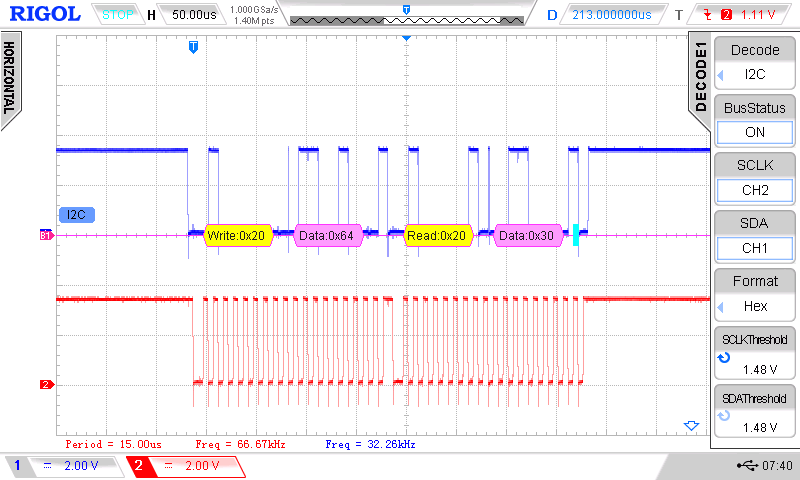
The Python lib is working correctly as the Osci screen shows. The program returns 0x30 as expected.
The problem is that no receive interrupt is generated by this read, so we have no possibility to read the command in our Arduino program. A simple workaround is to send first a write and then a read in the Python program:
   ...
    I2c.write_byte(PICO_I2C_ADDRESS,command)
    time.sleep(0.001)
    print(hex(I2c.read_byte_data(PICO_I2C_ADDRESS,command)))
    ...
Here is the Arduino code for the test:
    // pico_raspi_i2c_test.ino    weigu.lu

    #include <Wire.h>

    const byte PICO_I2C_ADDRESS = 0x20;
    byte volatile rx_flag = 0;
    byte volatile tx_flag = 0;
    byte volatile rx_buffer[] = {0,0,0,0,0,0,0,0,0,0};
    byte volatile tx_buffer[] = {0,0,0,0,0,0,0,0,0,0};

    void setup() {
      Serial.begin(115200);  // for debugging
      Wire.begin(PICO_I2C_ADDRESS);    // join i2c bus
      Wire.onReceive(i2c_receive);     // i2c interrupt receive
      Wire.onRequest(i2c_transmit);    // i2c interrupt send
    }

    void loop() {
      if (rx_flag) {
        for (byte i=0; i<rx_flag; i++) {
          Serial.print("RX: ");
          Serial.print(rx_buffer[i]);
          Serial.print('\t');
        }
        Serial.print('\n');
        rx_flag = 0;
      }

      if (tx_flag) {
        Serial.println("TX");
        Serial.println(rx_buffer[0]);
        tx_flag = 0;
      }
      delay(1);
    }

    void i2c_receive(int bytes_count) {  // bytes_count gives number of bytes in rx buffer
      for (byte i=0; i<bytes_count;i++) {
        rx_buffer[i] = Wire.read();
      }
      rx_flag = bytes_count;
    }


    void i2c_transmit() {
      tx_flag = 1;
      Wire.write("0");
    }
Downloads
Interesting links
