Tutorials:
Sensors, interfaces and bus systems (SENIN, BUSSY)
LoRa and LoRaWan
last updated: 2024-03-03
Quick links
- Introduction
- LoRa
- Simple LoRa p2p sender and receiver
- LoRa p2p transceiver
- LoRaWan
- Simple LoRaWAN device using TTN
- Getting MQTT data from TTN
- Interesting links
Introduction
LoRa and LoRaWAN are two new technologies in the world of the IoT, growing in popularity every year.
LoRa stands for Long Range and allows low-powered devices to communicate over long range wireless connections. LoRa is located on the physical (PHY) layer (bits) of the OSI model.

We can use LoRa for peer to peer to communication, meaning that two IoT devices talk together. We can use a Transmitter and a Receiver or two Transceiver if needed. The receiving device can e.g. save the data on an SD card or e.g. creating a website with graphs. Another possibility could be the use of the receiver as gateway e.g. to our local net (WiFi or Ethernet) and forward the data over MQTT.

To connect an IoT device (also called end device or node) wirelessly with a cloud respectively the Internet, we have 3 options:
We use a gateway that everyone already carries with them, the smartphone. We can use Bluetooth or WiFi to communicate with the smartphone and an app connects and sends data to the cloud.
We don't use a smartphone but an internal gateway. This can be our router (e.g. FritzBox) or a separate box from the device provider (e.g. Phillips Hue, Homematic, Devolo ...). Protocols used can be WiFi, DECT, Z-Wave, ZigBee etc..
We don't use a local gateway, but an external gateway.
If we want to connect many devices in a building with the cloud, the first option is not a good solution. The second option can be challenging because we have to cover the whole area, and the used technologies do not have a very long range. So we may need many repeaters for this.
For the third option we need a technology with a long range radio transmission to reach external gateways. We know such a technology, the mobile radio network (2G-5G). But the costs an resources of this network are high. Recent innovations in technology allow now to change this. They are known as Low-Power Wide-Area Network LPWAN. We get long range with low power and low cost.

One network already covering a the whole area in Luxembourg with gateways is Sigfox.
"Just do it" LoRaWAN 1:
- Search the net for Sigfox in Luxembourg. Which firms are involved? What are the costs? Document your findings.
- Search the net for Helium in Luxembourg. Which firms are involved? What are the costs? Document your findings.
- Search the net for The Things Network in Luxembourg. Document your findings.
Unfortunately thee costs to use Sigfox are high. But there is an alternative with lesser costs, mostly open source and full control: The Things Network TTN.
From the TTN website:
The Things Network consists of an inclusive and open community of people, companies, governments and universities who are learning, experimenting and building with The Things Stack to realize LoRaWAN solutions.

LoRaWAN is a network protocol resp. media access control (MAC) protocol for wide area networks. It is built upon LoRa® modulation technique and can be mapped to the second and third layer of the OSI model (data link and network layer for physical and logical addressing (frames and packets)).
LoRaWAN allows e.g. LoRa devices to communicate with Internet-connected applications. It is implemented on top of LoRa or FSK modulation in ISM radio bands. The LoRaWAN protocols are defined by the LoRa Alliance.
The Things Stack (V3) is a LoRaWAN Network Server developed by The Things Industries. The Things Stack is open source, runs on TTN server, but can also be used for small, local networks.
LoRa
Let's start with the physical layer LoRa.
Long Range, and refers to a new radio technology designed for the IoT, increasing the radio range and using very little power.LoRa beats other radio technologies like WiFi, ZigBee or Bluetooth in range and largely in power consumption (look here under comparing different wireless protocols). So normally some 100 meters in buildings are no problem, and LoRa devices can run for months or even years on battery. The LoRa radio receiver is very sensitive. It may receive signals many times weaker (down to -160 dBm) than other wireless technologies.
To achieve this performance a LoRa node will wake up perhaps once an hour, and send tiny data packet containing data. So most of the time (99.99 %) the LoRa node would be in an ultra-low-power sleep.
All this comes with a significant cost: The bit rate of LoRa is very much lower than the bit rate of other wireless technologies. Compared to other technologies, the biggest difference you’ll notice with LoRa is that even the advertised data rates are really low. LoRa can, depending on the channel configuration, handle bit rates of between 250 bit/s and 11 kbit/s (Europe). Besides this, it is a half-duplex transmission, so we get half the data rate of the channel if we don't use both directions and we can use this data rate only 1 % of the time of a day (1 % duty cycle). This 1 % duty cycle reduces the effective data rate to 55 bits/s!
ISM band
LoRa communication uses small parts of the radio spectrum initially reserved internationally for Industrial, Scientific and Medical purposes other than telecommunications called ISM radio bands. Nowadays these bands are often used for short-range, low power wireless communications systems to avoid government licenses needed to transmit on other frequency bands. Communications equipment operating in ISM bands must tolerate any interference generated other ISM applications. In Europe to use the ISM band (863 MHz - 870 MHz) users must accept the following restrictions:
- Uplink: the maximum transmission power is limited to 25 mW (14 dBm).
- Downlink (869.525 MHz), the maximum transmission power is limited to 0.5 W (27 dBm)
- Duty cycle (percentage of time a device is allowed to transmit): 0.1 % and 1 % per day depending on the channel (mostly 1 %).
- Maximum antenna gain: +2.15 dBi.
Besides these ISM band rules, the network operator (for example The Things Network) can also add additional restrictions.
LoRa properties and modulation
The radio part was developed by SEMTECH and is closed source.
CAD and TDMA
The LoRa radio has a feature which can wake it from a low power state when it detects the start of a message. Other radios need here a power consuming RSSI scan. This feature is called Channel Activity Detection (CAD) and allows a randomized Time-Division Multiple Access (TDMA).
TDMA allows several users to share the same frequency channel (ISM frequencies) by dividing the signal into different time slots. In LoRa the time-slots are generated asynchronously respecting the 1 % duty cycle. We rely on a statistical likelihood, that if devices only transmit for 1% of the time we can operate several devices at the same time without many collisions. So LoRa is designed for small packets of data sent infrequently, and we keep in mind, that LoRa does not guarantee message delivery (collisions may occur).
Power
The maximum transmit power in Europe is is limited by law to 25 mW. We must respect this if we built our own antennas with higher gain.
Radio Modulation and LoRa
LoRa uses a proprietary spread-spectrum modulation technique. It is derived from existing Chirp Spread Spectrum (CSS) technology and uses a fixed-bandwidth channel of either 125 KHz or 500 KHz. This big bandwidth allows to reduce power (Shannon).
The key LoRa modulation property is the [Spreading Factor SF].
With a higher spreading factor the energy of the total signal is spread over a wider range of frequencies, allowing the receiver to be more sensitive and to discern a signal with a lower signal-to-noise ratio (SNR) and so to increase the range.
Channel parameters
We get several channel parameters of a physical LoRa link that affect the signal conditions, the data rate and power constraints. These parameters must be the same for the sender and the transmitter, to be able to communicate.
- The channel number or Frequency (ISM 868)
We use the 868 MHz ISM band, and for Luxembourg we have the EU863-870 channel plan, meaning the frequencies lie between 863 MHz and 873 MHz. Their are no real predefined channels, so the network channels can be freely attributed. However, three default channels shall be implemented in every EU868MHz gateway. Those three channels are the minimum set that all network gateways shall be listening on.
Their are no real predefined channels. The Things Network (TTN) uses e.g. 868.1 MHz, 868.3 MHz and 868.5 MHz for their first 3 channels. It is important that the sender and the receiver use the same frequency!
The channel Bandwidth
Bin kHz (10.4, 15.6, 20.8, 31.25, 41.7, 62.5, 125, 250, 500)The Spreading Factor
SF(SF7, SF8, SF9, SF10, SF11, SF12)
The most significant parameter is the spreading factor. Increasing it will reduce the data rate (bit rate) but increase the range.The Code Rate
CR(0, 1, 2, 3, 4)
Code rate
In a crowded frequency spectrum interference will inevitably occur. If the signal is disturbed, a built-in forward error correction will help. The error correction always supplements 4 bits carrying information by 0 to 4 error correction bits, so that errors can be recovered at the reception. The coding rate can be adjusted from 0 to 4. It refers to the proportion of bits carrying information (often 4) over all the bits (4 + CR). The coding rate can be e.g. 4/4, 5/4 (default), 4/6 etc...
Simple LoRa p2p sender and receiver
We will start without gateway and WAN, with a simple radio communication.
Hardware
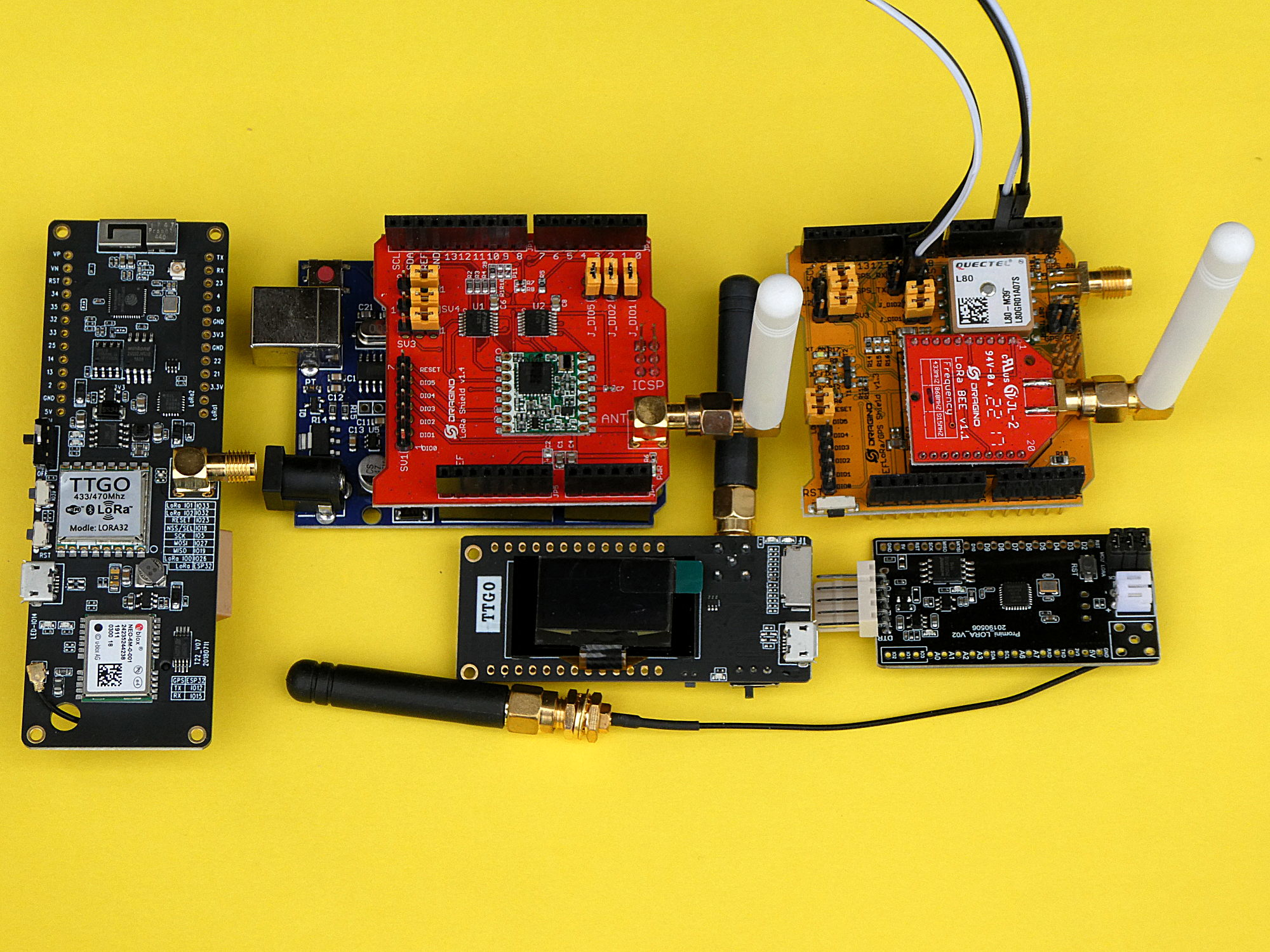
There exist many boards with a LoRa chip. In the following picture we see two Arduino shields (top right), one with supplementary GPS chip (Draguino). The left board, also with GPS has an ESP32 µC, as the board in the middle (bottom) with supplementary SD card slot and OLED display. The board at the right (bottom) is an Arduino (mega328) with LoRa but without USB/TTL chip.
Frequency
LoRa uses the license-free industrial, scientific and medical (ISM) bands. For Europe we get 433 MHz, and 868 MHz (915 MHz for Australia and North America and 923 MHz for Asia). We choose 868 MHz because this band is exclusively reserved for communication between wireless sensor networks. It is less used than 433 MHz and it is less likely to be interfered.
Higher frequencies result in shorter wavelengths. Theoretically 433 MHz can travel a greater distance than 868 MHz, but because of disturbances this often is not true. The antennas for 868 MHz are shorter.
It is clear, that only chips with the same frequency can operate together.
Breakout board
The chips used are from SEMTECH. For own solutions we can use the SX1276 chip that can be bought on a breakout board RFM95W-V2.0 from hoperf (specification document). Unfortunately the board uses a 2 mm pin header pitch instead of the usually used 2.54 mm (0.1 in). So we need an additional breakout board to be able to use the chip on a breadboard.

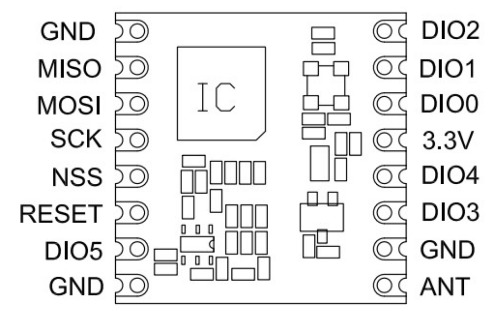
Connections:
Don't forget to connect the antenna before powering the board! Without antenna the board can be damaged!
If you don't have an antenna, use a wire with 8.2 cm in length.
The board uses the SPI interface (MISO, MOSI, SCK, SS (NSS)) to communicate with the microcontroller, and it is powered with 3.3 V (GND, +3.3 V).
For SPI we usually use the pins of the default SPI interface for MISO, MOSI and SCK. With the function SPI.begin() it is possible to change if a second interface is available. The chip select pin is freely selectable. The library uses by default pin 5 for the Uno. The DI00 pin (RFM95W) must be connected to a pin supporting interrupts, because the LoRa chip signals an incoming message with this output to the microcontroller (default Uno pin 2). Same for DI01, needed only for LoRaWAN (pin 6 for UNO). An output pin of the microcontroller can also be used to reset (RESET pin) the LoRa chip if needed.
Even if we find schematics connecting the Arduino Uno directly to the RFM95W board, this is not a valabel solution! The output pins (MOSI, CLK etc.) of the Uno have 5 V! One solution can be to use level shifters like on the Dragino shield, or to use voltage dividers for all outputs. A simpler solution is an Arduino Uno with 3V by changing the voltage regulator. We will use ESP boards for our exercises.
| LoRa breakout board (SX1276) | Arduino Uno (3 V!) | ESP8266 (WEMOS) | ESP32 |
|---|---|---|---|
| 3.3 V (Vin) | 3.3 V | 3.3 V | 3.3 V |
| GND | GND | GND | GND |
| MOSI | 11 | 14 | 23 |
| MISO | 12 | 12 | 19 |
| SCK | 13 | 13 | 18 |
| NSS (SS, CS) | 5 | 16 | 26 |
| RST (Reset) | 9 | not connected or 2 | not connected or 16 |
| DIO0 (G0, IRQ) | 2 | 15 | 5 |
| DIO1 (G1, IRQ) | 6 (only needed for LoRaWAN!) | 0 (only needed for LoRaWAN!) | 17 (only needed for LoRaWAN!) |
| DIO2-5 | not connected | not connected | not connected |
| ANT | antenna | antenna | antenna |
Software
We use the LoRa library from Sandeep Mistry. Information about the library can be found in the corresponding LoRa Application Programming Interface (API).
The software can be found on github: https://github.com/weigu1/lora_p2p_SX1276_esp.
Here are two basic sketches for the sender (transmitter):
    /*
      lora_p2p_esp_sx1276_simple_sender_868.ino

      weigu.lu 2024

      ESP32:   MH ET LIVE ESP32-MINI-KIT  with RFM95W (SX1276)
      ESP8266: WEMOS D1 mini pro with RFM95W (SX1276)

          MH ET Live   |---|   Mini Kit              WEMOS |---| D1 Mini Pro

      GND    |  RST    |---|  3 RxD  |    GND        RST         |---|       TxD
       NC    |  SVP 36 |---|  1 TxD  | 27                 A0     |---|       RxD
      SVN 39 |      26 |---| 22 SCL  | 25                 D0 16  |---|  5 D1 SCL
          35 |  SCK 18 |---| 21 SDA  | 32             SCK D5 14  |---|  4 D2 SDA
          33 | MISO 19 |---| 17 TxD2 | 12 TDI        MISO D6 12  |---|  0 D3
          34 | MOSI 23 |---| 16 RxD2 |  4            MOSI D7 13  |---|  2 D4 LED
      TMS 14 |   SS  5 |---|    GND  |  0              SS D8 15  |---|       GND
       NC    |  3V3    |---|    5V   |  2            3V3         |---|        5V
      SD2  9 |  TCK 13 |---| 15 TD0  |  8 SD1
      CMD 11 |  SD3 10 |---|  7 SD0  |  6 CLK

      LoRa board     | ESP8266  | ESP32 |
      3.3V (Vin)     | 3.3V     | 3.3V
      GND            | GND      | GND
      MOSI           | 14       | 23
      MISO           | 12       | 19
      SCK            | 13       | 18
      NSS (SS, CS)   | 16       | 5
      RST (Reset)    | nc       | 33
      DIO0 (G0, IRQ) | 15       | 26
      DIO1 (G1, IRQ) | only WAN | only needed for LoRaWAN!
      DIO2-5         | nc       | not connected (nc)
      ANT            | antenna  | antenna

      freq = 868MHz, SPI pins are default pins MOSI=13/23, MISO=12/19, SCK=14/18
    */

    #include <SPI.h>
    #include <LoRa.h>

    #ifdef ESP8266
      const byte PIN_SS =  16;    // LoRa radio chip select
      const byte PIN_RST = -1;    // LoRa radio reset (not connected)
      const byte PIN_IRQ = 15;   // hardware interrupt pin!
    #else
      const byte PIN_SS =  26;
      const byte PIN_RST = -1;
      const byte PIN_IRQ =  5;
    #endif // #ifdef ESP8266

    //const byte PIN_SCK =  18;
    //const byte PIN_MISO = 19;
    //const byte PIN_MOSI = 23;

    unsigned int counter = 0;

    void setup() {
      Serial.begin(115200);
      Serial.println("LoRa sender\n");
      //SPI.begin(PIN_SCK, PIN_MISO, PIN_MOSI, PIN_SS); //if not default pins
      LoRa.setPins(PIN_SS, PIN_RST, PIN_IRQ);           // setup LoRa transceiver
      if (!LoRa.begin(868E6)) {
        Serial.println("Error starting LoRa!");
        while (true);                                   //endless loop
      }
    }

    void loop() {
      Serial.print("Sending packet number: ");
      Serial.println(counter);
      LoRa.beginPacket();
      LoRa.print("This is packet number ");
      LoRa.print(counter);
      LoRa.endPacket();
      counter++;
      delay(60000);
    }
And the receiver (polling):
    /*
      lora_p2p_esp_sx1276_simple_receiver_868.ino

      The receiver uses polling. Look at the transceiver example for callback.
    */

    #include <SPI.h>
    #include <LoRa.h>

    #ifdef ESP8266
      const byte PIN_SS =  16;    // LoRa radio chip select
      const byte PIN_RST = -1;    // LoRa radio reset (not connected)
      const byte PIN_IRQ = 15;   // hardware interrupt pin!
    #else
      const byte PIN_SS =  26;
      const byte PIN_RST = -1;
      const byte PIN_IRQ =  5;
    #endif // #ifdef ESP8266

    //const byte PIN_SCK =  18;
    //const byte PIN_MISO = 19;
    //const byte PIN_MOSI = 23;

    byte packet_size = 0;

    void setup() {
      Serial.begin(115200);
      Serial.println("LoRa receiver\n");
      //SPI.begin(PIN_SCK, PIN_MISO, PIN_MOSI, PIN_SS); //if not default pins
      LoRa.setPins(PIN_SS, PIN_RST, PIN_IRQ);           // setup LoRa transceiver
      if (!LoRa.begin(868E6)) {
        Serial.println("Error starting LoRa!");
        while (true);                                   //endless loop
      }
    }

    void loop() {
      packet_size = LoRa.parsePacket();         // try to parse packet
      if (packet_size) {  // received a packet
        Serial.print("Received packet with ");
        Serial.print(packet_size);
        Serial.print(" byte: '");
        while (LoRa.available()) {              // read packet
          Serial.print((char)LoRa.read());
        }
        Serial.print("' with RSSI = ");
        Serial.print(LoRa.packetRssi());
        Serial.println("dBm");
      }
    }
"Just do it" LoRaWAN 2:
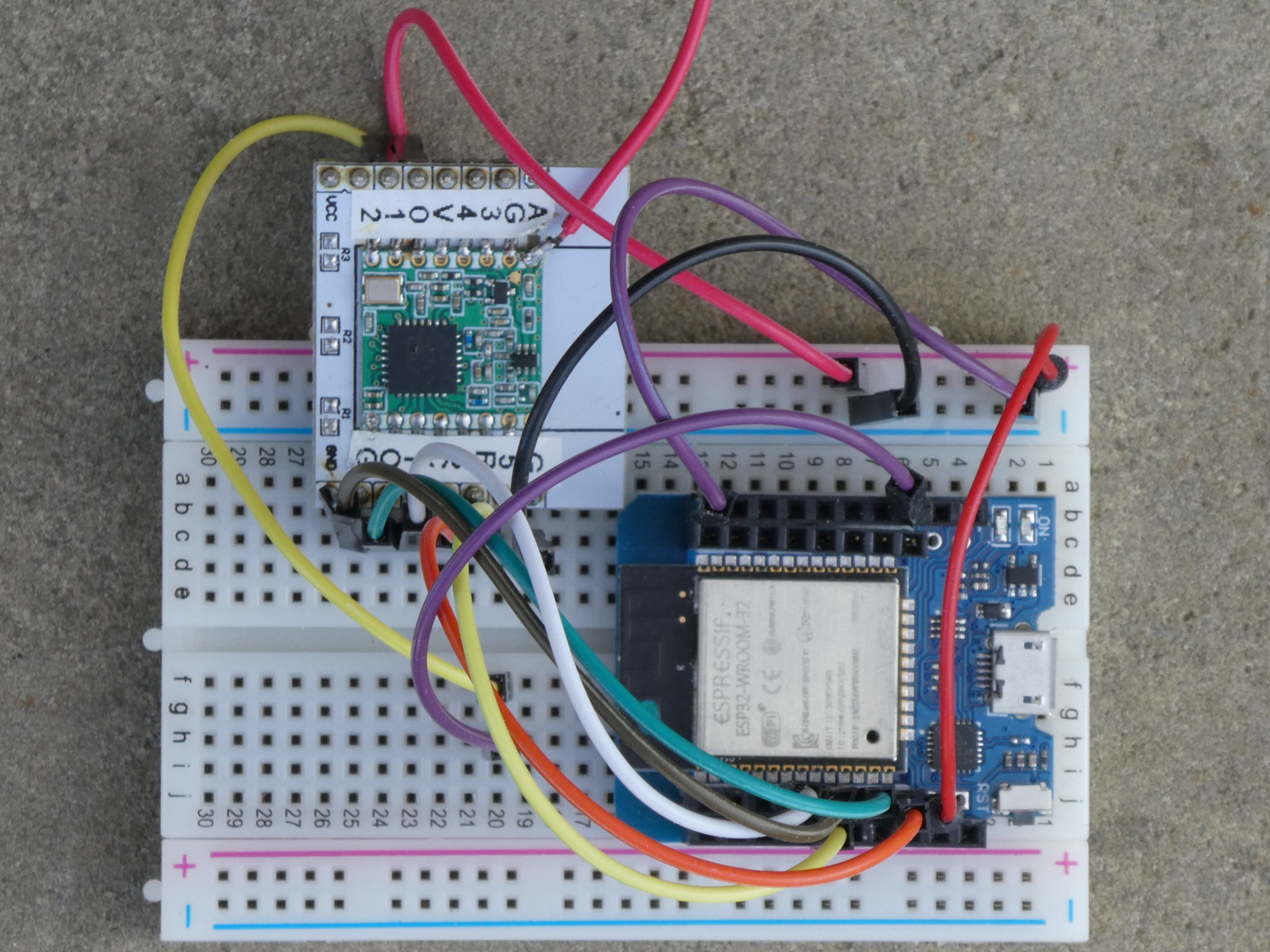
For this exercise we will 2 LoRa boards (ESP32 with breakout board RFM95W-V2.0) as receiver and transmitter. One of the boards must be build up on a breadboard using wires. Document your circuits with a photo. Test the sketches above. Document the serial output of the receiver.
Add a 1-Wire temperature sensor (
DS18B20) to the transmitter and send the temperature as message. Document the sketch of the transmitter and the serial output of the receiver.
LoRa p2p transceiver
The following sketch shows how a transceiver can be build with duplex communication and callbacks. Transmitter and receiver use a unique address (only 1 byte = 256 addresses, 0xFF for broadcast messages). The message gets an identifier (ID), realised in the sketch with a simple message counter. The delay time between sends is not static (randomized) to avoid collisions.
    /*
      lora_p2p_esp_sx1276_transceiver_868.ino

      LoRa duplex communication with callback
    */

    #include <SPI.h>
    #include <LoRa.h>

    #ifdef ESP8266
      const byte PIN_SS =  16;    // LoRa radio chip select
      const byte PIN_RST = -1;    // LoRa radio reset (not connected)
      const byte PIN_IRQ = 15;    // hardware interrupt pin!
    #else
      const byte PIN_SS =  26;
      const byte PIN_RST = -1;
      const byte PIN_IRQ =  5;
    #endif // #ifdef ESP8266

    const byte NODE_ADDR = 0x01;                 // address of this device
    const byte GATEWAY_ADDR = 0xFE;              // 0xFE=gateway, 0xFF=broadcast
    unsigned long send_delay = 60000;            // delay in ms between sends
    byte msg_out_id = 0;                         // cnt of outgoing msgs = msg id

    byte addr_in_rec, addr_in_sender, msg_in_id, msg_in_length;
    String message, msg_out, msg_in, lora_rssi, lora_snr;
    volatile bool flag_message_received = false; // flag set by callback

    void setup() {
      Serial.begin(115200);
      Serial.println("LoRa duplex with callback\n");
      LoRa.setPins(PIN_SS, PIN_RST, PIN_IRQ);           // setup LoRa transceiver
      if (!LoRa.begin(868E6)) {
        Serial.println("Error starting LoRa!");
        while (true);                                   // endless loop
      }
      LoRa.onReceive(onReceive);                        // init the callback func.
      LoRa.receive();                                   // start receive mode
    }

    void loop() {
      LoRa.receive();                            // go back into receive mode
      if (flag_message_received) {               // if recv flag set by callback
        readMessage();
        flag_message_received = false;           // set flag back to false
      }
      if (non_blocking_delay(send_delay)) {      // send a message all delay ms
        message = "HeLoRa World!";
        send_message(message);
        Serial.println("Sending:");
        Serial.print("GW addr.: ");
        Serial.print(GATEWAY_ADDR);
        Serial.print(" (1 byte) + node addr.: ");
        Serial.print(NODE_ADDR);
        Serial.print(" (1 byte) + msg ID: ");
        Serial.print(msg_out_id);
        Serial.println(" (1 byte) +");
        Serial.print("msg length: ");
        Serial.print(message.length());
        Serial.println(" (1 byte) + message: \"" + message + "\"");
        Serial.println("-------------------------------------------------------");
        send_delay = send_delay + random(1000);  // randomize  to avoid collisions
      }
      delay(1);
    }

    // callback function
    void onReceive(int packetSize) {
      if (packetSize == 0) {                // if there's no packet, return
        return;
      }
      flag_message_received = true;         //Set flag to perform read in main loop
    }

    // send the message and increment ID
    void send_message(String message_out) {
      LoRa.beginPacket();                   // start packet
      LoRa.write(GATEWAY_ADDR);             // add destination address
      LoRa.write(NODE_ADDR);                // add sender address
      LoRa.write(msg_out_id);               // add message ID (counter)
      LoRa.write(message_out.length());     // add payload length
      LoRa.print(message_out);              // add payload
      LoRa.endPacket();                     // finish packet and send it
      msg_out_id++;                         // increment message counter (ID)
    }

    // read a message and check if valid
    void readMessage() {
      addr_in_rec = LoRa.read();            // recipient address
      addr_in_sender = LoRa.read();         // sender address
      msg_in_id = LoRa.read();              // incoming msg ID
      msg_in_length = LoRa.read();          // incoming msg length
      while (LoRa.available()) {
        msg_in = LoRa.readString();
        yield();
      }
      if (msg_in_length != msg_in.length()) {// check length for error
        Serial.println("error: message length does not match length");
        return;
      }
      if (addr_in_rec != GATEWAY_ADDR && addr_in_rec != 0xFF) {
        Serial.println("This message is not for me.");
        return;
      }
      lora_rssi = LoRa.packetRssi();
      lora_snr = LoRa.packetSnr();
      Serial.print("From: 0x" + String(addr_in_sender, HEX));
      Serial.print("\tto: 0x" + String(addr_in_rec, HEX));
      Serial.print("\tRSSI: " + lora_rssi);
      Serial.println("\tSnr: " + lora_snr);
      Serial.print("Message: " + msg_in);
      Serial.print("\tLength: " + String(msg_in_length));
      Serial.println("\tID: " + String(msg_in_id));
      Serial.println("-------------------------------------------------------");
    }

    // non blocking delay using millis(), returns true if time is up
    bool non_blocking_delay(unsigned long milliseconds) {
      static unsigned long nb_delay_prev_time = 0;
      if(millis() >= nb_delay_prev_time + milliseconds) {
        nb_delay_prev_time += milliseconds;
        return true;
      }
      return false;
    }
"Just do it" LoRaWAN 3:
Read the wiki page about callbacks.
A transceiver with temperature sensorDS18B20and the address0x01sends the temperature once every 5 minutes to a second transceiver acting as gateway (address0xFE). If the message is not valid (temperature not between 0 °C and 45 °C or a wrong message length) the gateway replies after 100 ms with the text"NACK"+ID. If the sender gets a "NACK"+ID it will resend the last message (ID) once. The gateway cares that "NACK"+ID is sent only once per message ID. Document the sketches and the outputs.Look at the library examples "LoRaSimpleGateway.ino" and "LoRaSimpleNode.ino" (Arduino IDE). Explain in detail what is done in these sketches.
LoRaWan
As seen in the introduction, we need a gateways and a server on the internet. We will use the The Things Network TTN. There exist indoor and outdoor gateways for the TTN. The prices range roughly from 50 € to 500 €.
TTN frequency plans EU863-870
| Channel | frequency [MHz] | spreading factor and bandwidth |
|---|---|---|
| 1 | 868.1 | SF7BW125 to SF12BW125 |
| 2 | 868.3 | SF7BW125 to SF12BW125 and SF7BW250 |
| 3 | 868.5 | SF7BW125 to SF12BW125 |
| 4 | 867.1 | SF7BW125 to SF12BW125 |
| 5 | 867.3 | SF7BW125 to SF12BW125 |
| 6 | 867.5 | SF7BW125 to SF12BW125 |
| 7 | 867.7 | SF7BW125 to SF12BW125 |
| 8 | 867.9 | SF7BW125 to SF12BW125 |
| 9 | 868.8 | FSK |
The Things Stack Community Edition (V3) is a LoRaWAN Network Server developed by The Things Industries. The Things Stack is open source, runs on TTN server, but can also be used for small, local networks (e.g. Docker Container on a Raspberry Pi).
Activation modes OTAA and ABP
There exist 2 activation modes for LoRaWAN end devices called ABP and OTAA. OTAA is recommended by The Things Stack (explanations here).
For all the new terms and definitions the following glossary is a good help:
https://www.thethingsindustries.com/docs/reference/glossary/.
To understand activation we must understand the meaning of the following ID and address:
DevEUI:
Every end device (hardware) needs a 64-bit Extended Unique IDEUI! This ID is calledDevEUIand is assigned by the manufacturer and cannot be altered.DevAddr:
And end device needs a 32-bit Address. TheDevAddridentifies the end device within the network and all communication after joining the network is done with it. It consists of an network addressNwkAddrprefixed by a network identifierNwkID.
During the activation process a DevAddr and session keys are assigned to an end device.
LoRaWAN supports two modes of activating an end device:
Activation By Personalization ABP
An immutable DevAddr and immutable Session keys for a pre-defined network are hardcoded into the end device. There is no need for a join procedure. This can be an advantage with battery powered devices or devices who have a low RSSI (less energy needed).
Over-The-Air Activation OTAA
OTAA activation means that an end device performs a join procedure with the LoRaWAN network. A dynamic DevAddr is assigned to the device during the activation. Session keys are derived from root keys that are hard coded in the device. With every session the DevAddr and session keys change.
"Just do it" LoRaWAN 4:
- Read the article "OTAA and ABP". Explain why
OTAAis more secure in your own words. What problems can occur with the frame counter if we useABP?
OTAA negotiates new keys when connecting . The end device sends a Join Request (JR) to the gateway and receives the session keys per Join Accept (JA).
The Application EUI AppEUI, the device EUI DevEUI and the Application key AppKey are registered on the TTN server. If we buy a device the OTA data can mostly be found on the housing or in the description of the product.
Simple LoRaWAN device using TTN
Hardware
We use the same node than in our previous exercise, meaning an ESP32 (MHETLive) with the hoperf breakout board (SX1276) and a oneWire DS18B20 temperature sensor connected to pin 27 and 3.3V (don't forget the pull-up resistor of e.g. 1.8k). Use the following connections for the LoRa breakout board:
| LoRa breakout board (SX1276) | ESP32 |
|---|---|
| 3.3 V (Vin) | 3.3 V |
| GND | GND |
| MOSI | 23 |
| MISO | 19 |
| SCK | 18 |
| NSS (SS, CS) | 26 |
| DIO0 (G0, IRQ) | 5 |
| DIO1 (G1, IRQ) | 17 |
| ANT | antenna |
Software library
To implement LoRaWAN we need to use a LoRaWan library with a reduced footprint, because the memory in ATmega chips (Uno, Leonardo) is very limited. Install the MCCI LoRaWAN LMIC library by Terry Moore in the library manager. This library provides a fairly complete LoRaWAN Class A and Class B implementation (tested for V1.0.3 of the LoRaWAN specification) and is more up to date than the older LMIC-Arduino by IBM that is no longer maintained.
We have to tell the library what frequency and chip we use. For this we open the following file in the folder where your sketches are located:sketchbook/libraries/MCCI_LoRaWAN_LMIC_library/project_config/lmic_project_config.h
with an editor.
Then we uncomment (remove //) the following lines. All other lines must be commented (add //).
    // project-specific definitions
    #define CFG_eu868 1
    #define CFG_sx1276_radio 1
Connect to TTN and create an application
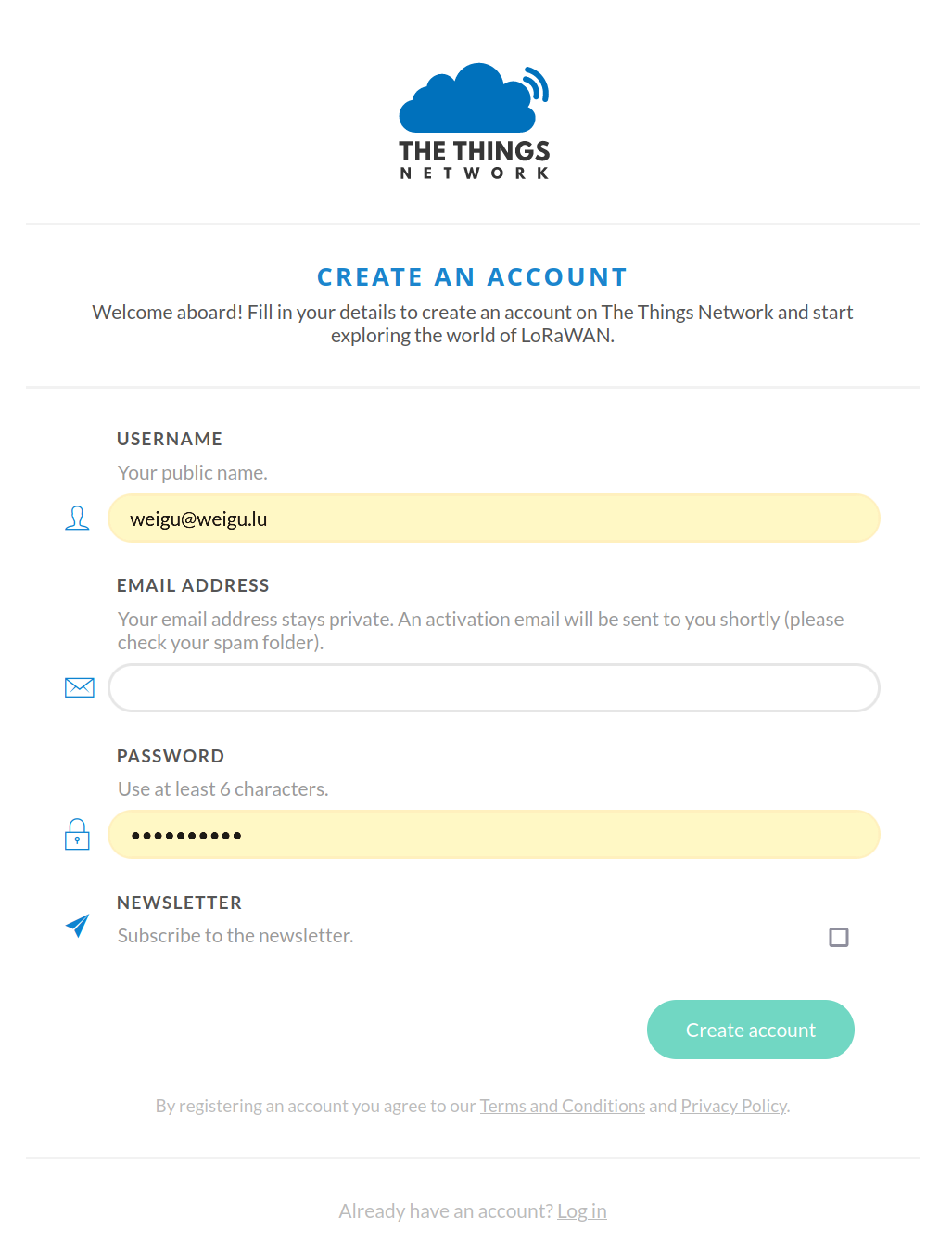
First, we must register an account with The Things Network (TTN). Navigate to the account registration page and set up an account.
When logged in, navigate to the TTN Console for Europe 1.

Before our LoRaWAN node can communicate with the network we need to create an Application. An application can contain one or more end devices. Under Go to applications we can add applications and add new devices.
Click on Go to applications and than on + Add application.

We give the application an Application ID. This ID must be unique and allows only lowercase alphanumeric characters and the dash '-' with a maximum of 36 characters. We can add a Name and a Descripton for the application. Both are optional. Click on Create application.
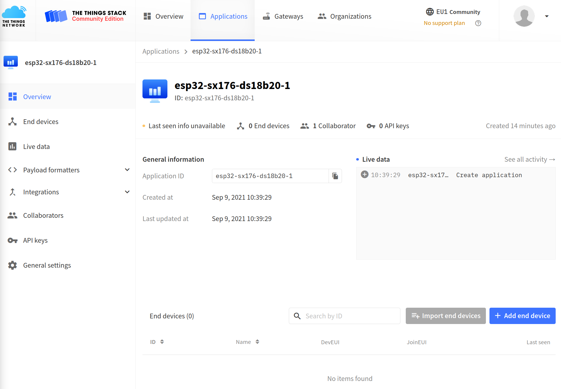
Now we see the Applications Overview. Click on + Add end device and select here the tab Manually.

Now we choose the LoRaWAN version 1.0.3 (see library) and the recommended frequency plan (Europe 863-870 MHz SF9 for RX). Now we can generate our 64 bit unique DevEUI if we don't want to create it ourself. The AppEUI or JoinEUI (not clear what is the right name for v3) can be filled with zeros, and we generate an Application Key AppKey.
A unique identifier for our device is created. We can accept the created ID or better change it to a more meaningful string.
In the advanced mode (not needed now) we could chose ABP or another class for the device.

After clicking on Register end device we get an updated End devices page. This page will help to copy the he DevEUI, the AppEUI and the AppKey to our Arduino sketch.
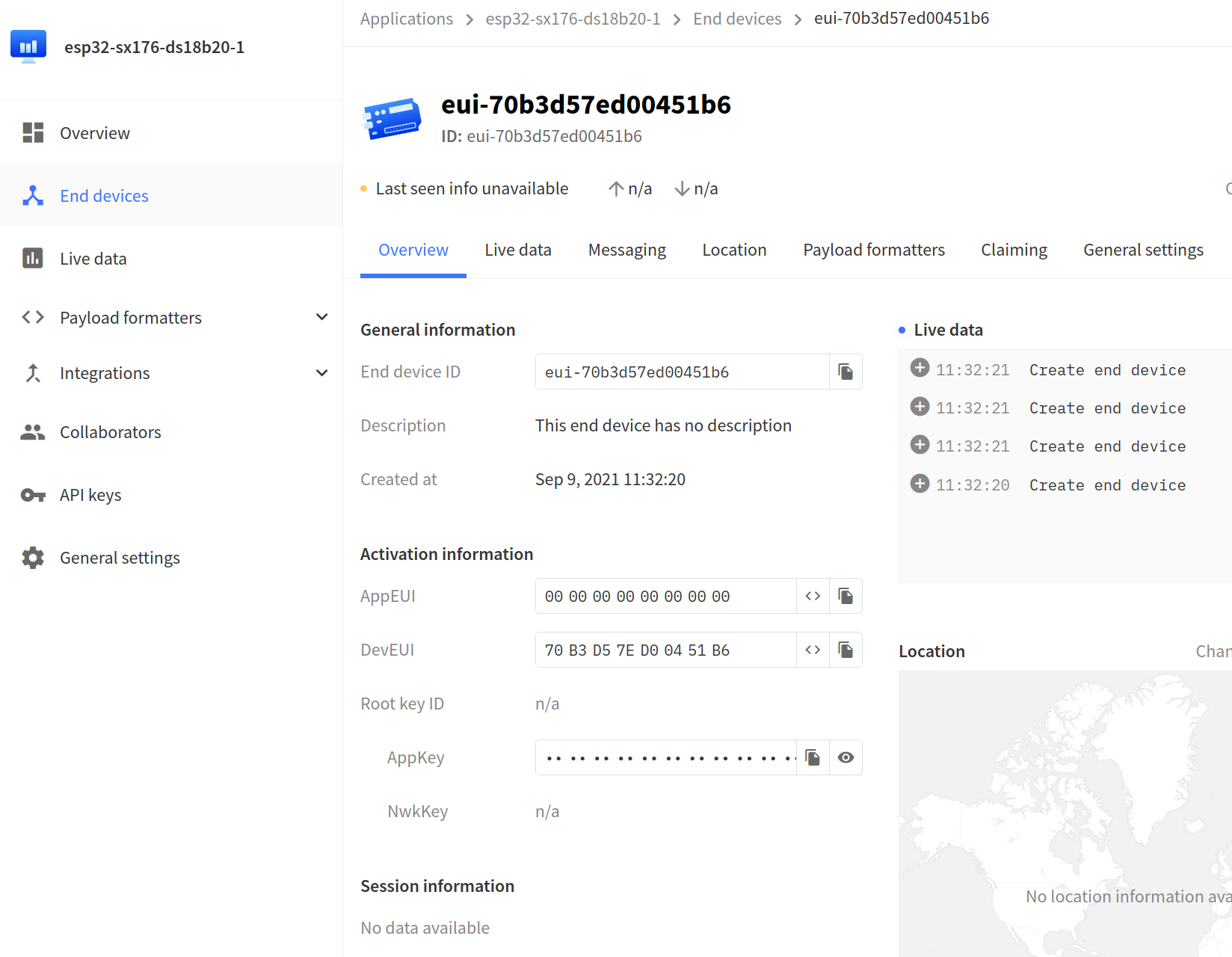
In the tab General settings we can add an optional End device name and an optional End device description.
Next we will see the DEVICE OVERVIEW page. We see that the activation method is OTAA. We also see the Application EUI, the Device EUI and the App Key (click on the eye) needed to communicate with the application. At the bottom of this page, we see a box called "Example Code". Wonderfully, this is a snippet of code that can directly be copied in our sketch.
Adjust the Arduino sketch
In Arduino we choose the ttn-otaa example from the LMIC library (File > Examples > MCCI LoRaWAN LMIC library).
In the OTAA mode (Over The Air Activation), we need to add to our sketch the DevEUI, the AppEUI and the AppKey. They are needed in an over-the-air activation procedure to generate a device address and session keys to be used with all further communication.
We can copy the needed informations from our TTN end device page by clicking on the right copy icon. In our sketch both EUIs need to be Little Endian meaning the Least Significant Byte (LSB) must be first. Click first on the most left-hand icon (<>) to get a C-style representation and then on the second left icon (two arrows) to change to LSB. Copy with the right icon and paste in the sketch (replace FILLMEIN). The AppKey can be copied as is.
We should see something like this after pasting:
    // APPEUI and DEVEUI LSB first! APPKEY MSB first!
    static const u1_t PROGMEM APPEUI[8]={ 0x00, 0x00, 0x00, 0x00, 0x00, 0x00, 0x00, 0x00 };
    void os_getArtEui (u1_t* buf) { memcpy_P(buf, APPEUI, 8);}
    static const u1_t PROGMEM DEVEUI[8]={ 0xB6, 0x51, 0x04, 0xD0, 0x7E, 0xD5, 0xB3, 0x70 };
    void os_getDevEui (u1_t* buf) { memcpy_P(buf, DEVEUI, 8);}
    static const u1_t PROGMEM APPKEY[16] = { 0x9C, 0xE6, 0xAA, 0xE3, 0x80, 0x11, 0xE4,
                                             0x6C, 0x9B, 0xCE, 0x8D, 0xDC, 0xC2, 0x28, 0x41, 0x35 };
    void os_getDevKey (u1_t* buf) {  memcpy_P(buf, APPKEY, 16);}
Next we must configure the right pins for our breakout board. For LoRa we didn't need the second interrupt pin DIO1. Here we must use it to detect an RX from the Things Network. Connect it to the digital pin 17. The SPI pins are the default ones.
| LoRa board | ESP32 |
|---|---|
| NSS (SS, CS) | 26 |
| RST (Reset) | 16 |
| DIO0 (G0, IRQ) | 5 |
| DIO1 (G1, IRQ) | 17 |
Replace the pin mapping in the example sketch:
    // Pin mapping
    const lmic_pinmap lmic_pins = {
      .nss = 26,                       //NSS and DIO0 are required
      .rxtx = LMIC_UNUSED_PIN,
      .rst = 16,
      .dio = {5, 17, LMIC_UNUSED_PIN},  //DIO1 is required for LoRa
    };
Because the clock of the Arduinos or ESPs are not accurate enough, add the following two lines to setup() (we also disable link-check mode, insert after Serial.println()):
    LMIC_setLinkCheckMode(0); //Disable link-check mode and ADR.
    LMIC_setClockError(MAX_CLOCK_ERROR * 1 / 100);
Now run the sketch.
In our serial monitor we should see the following text:
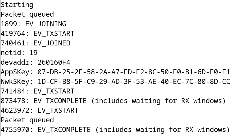
We can see the joining process and also the two assigned session keys.
And in the TTN console under Live data we see after the joining our data. If we want to see more infos we can switch on the verbose mode.
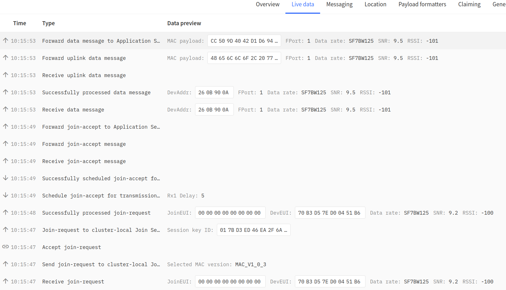
To decode the payload we need the ASCII table (0x48 = 'H', 0x65 = 'e', ...). To see the text we could add a decoder function under the Payload formatters.
By clicking on the line we get the Event details:
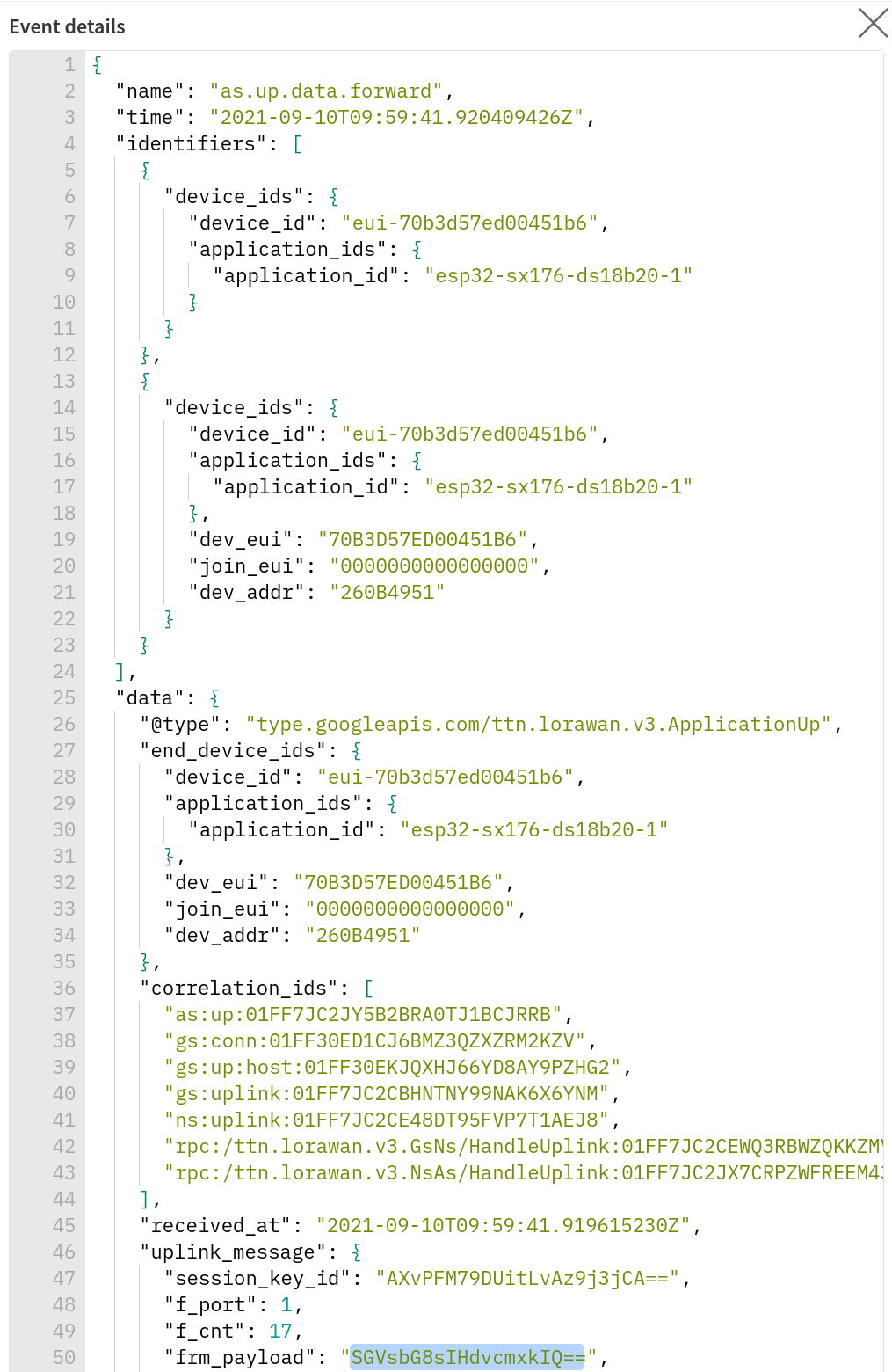
Interesting informations to estimate the quality of our transmission are the RSSI and SNR values and the "consumed_airtime" (under event details). We can also see that the spreading factor is SF7 and the bandwidth is 125 MHz.
In Event details we also find the payload "SGVsbG8sIHdvcmxkIQ==" (frm_payload), but can't read it, because it is encoded in Base64. More infos about this below (Getting MQTT data from TTN).
"Just do it" LoRaWAN 5:
- Extend the sketch to acquire the temperature from the connected
DS18B20. Send the temperature every 10 minutes toTTN. Document the sketch, the serial monitor and the Console data of TTN with payload and transmission data.
Getting MQTT data from TTN
One cool thing about TTN are their Integrations. Here we will look at the MQTT integration: https://www.thethingsindustries.com/docs/integrations/mqtt/.
The Application Server exposes an MQTT server. In order to use the MQTT server we need to create an API key. Go to Integrations MQTT and click on Generate new API key.
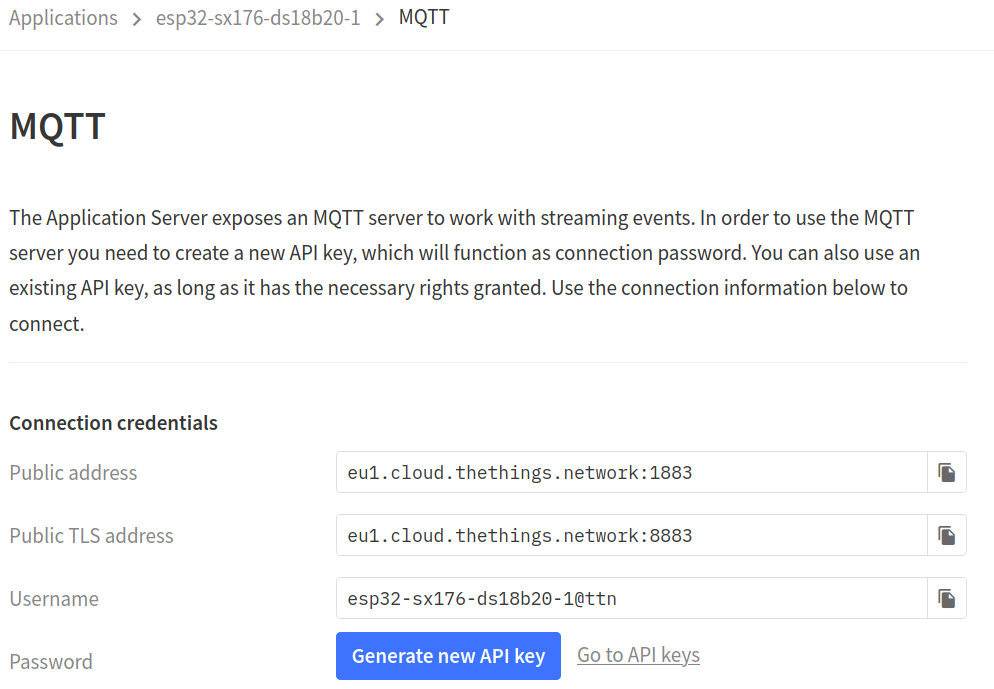
The server address is eu1.cloud.thethings.network (port 1883 or encrypted 8883). We have to provide a user name and a password.
The user name is the AppID@ttn and the password is the generated API key. This very long key can be copied with the icon on the right.
After this we can subscribe to our topic: v3/<AppID>/devices/<DevID>/up.
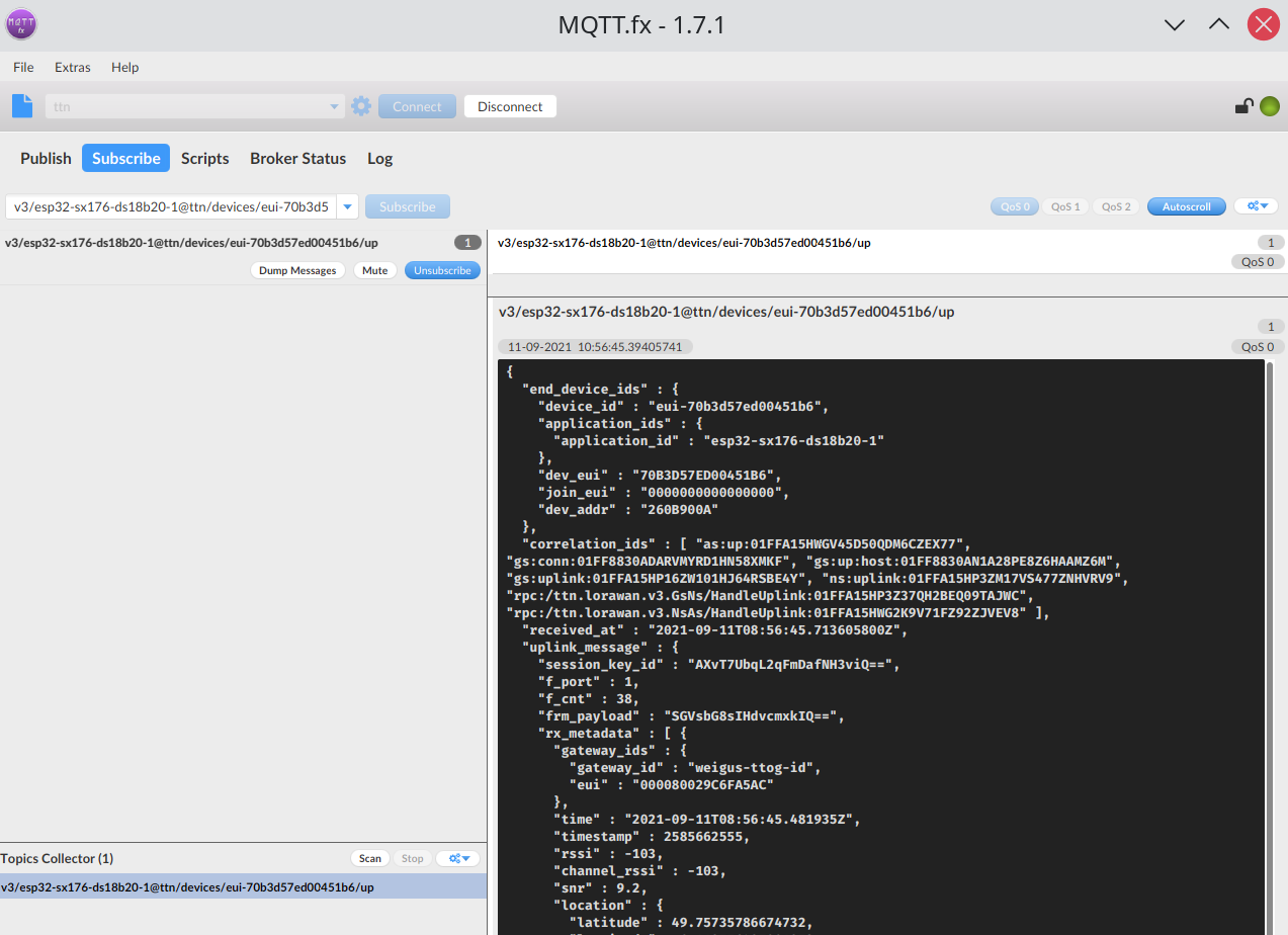
We get now all the data in a neat json format. Under frm_payload we find our payload: "SGVsbG8sIHdvcmxkIQ==". Ok this is not self explaining :)).
The payload is encoded in Base64. Letters , numbers, '+' and '/' are used to encode a 6 digit binary number (26 = 64) ('=' is used for padding). Let's look at our first 4 characters (use the table from the Base64 wiki page):
"SGVs" = 010010 000110 010101 101100.
If we regroup and use the ASCII table we get:
01001000 01100101 01101100 = 0x48 0x65 0x6C = 'H' 'e' 'l'.
For simplicity We can use an online decoder or the console in Linux with:
echo SGVsbG8sIHdvcmxkIQ== | base64 --decode
In a sketch we can use the Arduino library base64.
"Just do it" LoRaWAN 6:
- Get your data with MQTT Explorer. This software allows to create diagrams from topics. Create a diagram with the
RSSIand with theSNR. Document the diagrams (min 10 values). - Write an Arduino sketch to fetch the MQTT data and to decode the payload. Document the sketch.
Interesting links
- https://en.wikipedia.org/wiki/ISM_band
- https://en.wikipedia.org/wiki/LoRa
- https://de.wikipedia.org/wiki/Long_Range_Wide_Area_Network
- https://lora-alliance.org/about-lorawan
- https://fr.wikipedia.org/wiki/LoRaWAN
- https://github.com/leedowthwaite/SimpleLoRaGateway
- https://lora.readthedocs.io/en/latest/
- http://ttn.org/
- https://www.thethingsindustries.com/docs/reference/glossary/
- https://www.thethingsnetwork.org/docs/applications/mqtt/quick-start.html
- https://www.thethingsnetwork.org/docs/applications/mqtt/api.html
- https://www.thethingsnetwork.org/docs/lorawan/frequency-plans.html
