Tutorials:
Sensors, interfaces and bus systems (SENIN, BUSSY)
TIA-232 (wiki)
last updated: 2022-01-22
Quick links
Introduction
Song of this chapter: Gordon Lightfood > Summertime Dream > Protocol
We will try in this chapter to understand one protocol in depth. This will give us a basic knowledge that we can transfer to other protocols.
Sometimes a little history helps to better understand why things are what they are.
S.F.B. Morse made a first practical fully serial binary system with his Morse Code (first only uppercase letters). Morse's first system had a needle contacting a rotating drum of paper that made a continuous mark. With an electromagnet it was possible to lift the needle away from the paper creating a space. Telegraph operators noticed that the sound the needle made when scratching the paper was enough to get the message ans so the drum was replaced by a speaker. The terms MARK and SPACE are still used in the RS-232 standard.
The Recommended Standard 232 (RS-232) was originally introduced in 1960 as telecommunication standard. The standard was needed to connect electromechanical teletypewriters (or dumb computer terminals), called data terminal equipment (DTE) to a data communication equipment (DCE, also data circuit-terminating equipment) like a modem.
The modulator-demodulator (modem) was necessary to transmit digital signals which need a huge bandwidth (see Fourier in ELEFU) over the telephone line witch had only 3.4 kHz of bandwidth. The simplest method is a frequency-shift keying FSK modulation, where we use 2 sine tones (e.g. 1 kHz for LOW and 2 kHz for HIGH) to represent the two binary states.
At this time (1961) over sixty different ways of representing characters were used, and machines from different manufacturers could not communicate with one another. An IBM engineer (Bob Bemer) contacted the American National Standards Institute (ANSI) to develop a single code for computer communication. The American Standard Code for Information Interchange ASCII was released to serve as a common language among computers. It consists of 32 control characters like linefeed (LF, 0x0A) or carriage return (CR, 0x0D) to control the teletypewriter or terminal) and 96 characters—letters, numbers, or punctuation marks. With the limits of seven-bit hardware from that time, ASCII represents each of the 128 characters with a numeric value.
When computer terminals began to be used, they often had to be interchangeable with teletypewriters, and so supported RS-232. Later personal computers got an RS-232-compatible port for serial communications and used the standard for mice and keyboards. After the year 2000, USB took over. USB to serial adapters and cables are used today to connect serial devices to a computer. RS-232 is because of its simplicity still used widely on microcontroller, but also in networking equipment, industrial machines, and scientific instruments where a point-to-point, low-speed and wired data connection is adequate.
TIA-232
Signals and connectors
Data and control signals
Commonly used RS-232 signals and pin assignments for DB-25 and DB-9 connectors:
| DB-9 | DB-25 | Signal | Name | Purpose | Line | DTE↔DCD | Logic |
|---|---|---|---|---|---|---|---|
| 1 | 8 | DCD |
Data Carrier Detect | DCE is receiving a carrier on the line | message | ← | positive |
| 2 | 3 | RxD |
Received Data | Carries data from DTE to DCE | data | ← | negative |
| 3 | 2 | TxD |
Transmitted Data | Carries data from DTE to DCE | data | → | negative |
| 4 | 20 | DTR |
Data Terminal Ready | DTE is ready to receive, initiate, or continue a call. | control | → | positive |
| 5 | 7 | GND |
Ground | Signalground | ground | ||
| 6 | 6 | DSR |
Data Set Ready | DCE is ready to receive and send data | message | ← | positive |
| 7 | 4 | RTS |
Request To Send | DTE requests the DCE prepare to transmit data | control | → | positive |
| 8 | 5 | CTS |
Clear To Send | DCE is ready to accept data from the DTE | message | ← | positive |
| 9 | 22 | RI |
Ring Indicator | message | ← | positive |
All the signals are named from the standpoint of the DTE. We get two data lines, two control lines (DTE to DCE) and 4 message lines (DCE to DTE). The RS-232 control and message lines have a positive logic (3-15 V = HIGH), and the data lines a negative logic (3-15V = LOW). On the microcontroller side we get the opposite!
Connectors and cables
The first computer and modem used the D-subminiature 25-pin connector recommended by the first revisions of the standard. Later the DB-25M connector (no more used today) was replaced with the smaller DE-9M connector (sometimes mistakenly called DB-9).
For computer the male connector was used (DB-25 female was the parallel port) and for the modem the female connector. So the straight connection cable from DTE to DCE uses a female connector (DTE (PC) side) and a male connector on the DCE side.
Null modem cable
Today as modems are seldom used with TIA-232 all practically all our devices are computer or microcontroller (e.g. in sensors). So TIA-232 connects two DTE! and the sender must be connected to the receiver and vis-versa meaning the cables must be crossed!
Two null-modem cables:
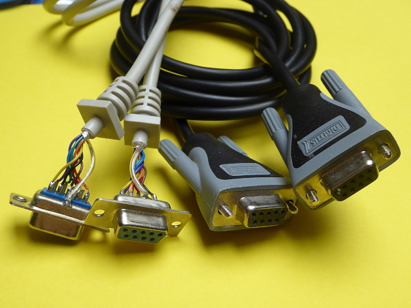
The simplest null modem cable (and most used today) has only three lines:
Hardware handshake
To better understand the control and message lines, let's look at a standard hardware handshake used between DTE and DCE (part of the protocol of TIA-232). This handshake was necessary because the modem usually was slow and could not manage the fast data stream, so the handshake helped to control the data stream and avoid a buffer overflow. As seen, all the signals are named from the standpoint of the DTE (which can be a sender, receiver or both).
- The most important lines are
TxDandRxDtogether withGND. Most connections today use only these three lines (two lines if a simplex connection suffices). - The DTE activates the control line
DTR(data terminal ready) to signalise that the DTE is switched on and ready to communicate. - After this the DCE answers with
DSR(data set ready) if the DCE is switched on and ready to communicate. - The flow control begins with a
RTS(request to send) from DTE (ready to send) and aCTS(clear to send) from the DCE. With this line the DCE can stop the data stream if a buffer overflow risks to happen. DCD(data carrier detect) andRI(ring indicator) are message lines to communicate the state of the telephone line, and are no more used Today
Here a possible time diagram for handshake signals measured on the microcontroller side (control lines use negative logic and are active LOW).
Programming a chip with Arduino
Today if control or message lines are used, it is normally a proprietary use and not the use meant by the standard. A good example is the Arduino platform.
Serial communication is used to program e.g. the controller (ATmega328p) on the Arduino Uno (R3) board. This is done over USB, so we find an USB-Serial converter chip (realised with an ATMega16u2) on the Arduino Uno board.
When the microcontroller gets reset, the bootloader checks to see if there is a new program waiting to be installed (by checking the serial data lines). If a new program is ready, the bootloader overwrites the existing program with the program and hands control over to it. If no program is waiting, the bootloader does nothing and allows the serial connection to run as normal.
Uploading a sketch is possible without having to physically press the reset button. The Arduino software automatically resets the board before starting the upload. This is done with the help of the DTR line. It is connect through a capacitor to RESET.
"Just do it" TIA1:
- Search for the circuit of Arduino Uno R3 and document (picture with comments) the part of the circuit which uses
DTRto reset the chip.
With this knowledge and a corresponding bootloader it is easy to "Arduinoize" other microcontroller like e.g. an ATmega8, ATmega32 ot ATmega644p. Programming can then be done with e.g. an USB to Serial cable that has beneath the data lines also a DTR line. You can find an example of such an "Arduinoizing" here.
Arduino also uses DTR and RTS to program ESP8266 and ESP32 chips. The needed circuit is already integrated on most Boards. To program a bare chip you need an ESP programmer (USB-Serial converter with 3 V and 2 control lines).
Software handshake
If no hardware handshake is possible a software handshake can be used to control the data flow. The two commonly used methods for TIA-232 are
XON/XOFF and ETX/ACK. Software handshake is seldom used today.
XON/XOFF
With two ASCII control codes XON and XOFF (X for transmitter or transmission) the data flow can be controlled by switching the transmission on or off, respectively.
If the input buffer of the receiver starts to become full the data is stopped with the XOFF character. When enough space appears in the buffer XON is sent to resume the data flow.
Mostly the ASCII codes DC1 (0x11) for XON and DC3 (0x13) for XOFF are used.
ETX/ACK
A second method uses the ASCII codes End of TeXt ETX (0x03) and ACKnowledgment ACK (0x06). With this half duplex method the data is separated into blocks (often 128 byte, depending on the buffer capacity) and after each block "End of TeXt" will be sent to show the end of this block of text.
If the data is accepted by the receiver and there is sufficient space in the input buffer an acknowledgement control code is sent. After this the next data block is sent.
The receiver also shows with the DTR line that he is ready.
Disadvantages of a software handshake
We need more extra characters. This makes the communication less effective. To send binary data is not possible without recoding because control codes are used (not all 256 characters are available).
Voltage levels
With a TTL voltage of 5 V or even only 3.3 V from ESP microcontroller it is, because of the surrounding noise and voltage drop due to losses, difficult to cover long distances with a serial signal. So TIA-232 specifies other voltage levels:
The voltages lies between -3 V and -15 V and between 3 V and 15 V, so avoiding ground. This makes it possible to detect if a connector is not plugged in or a cable is broken. The microcontroller signals are inverted. This results in data lines that are active HIGH (positive logic) and control and message lines that are active LOW on the microcontroller side.
In the following picture we see a signal on the microcontroller side (blue) and the same signal on TIA-232 (red). Two character of 8 bit (no parity, one stop bit (8N1)) are sent.
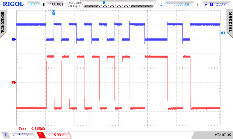
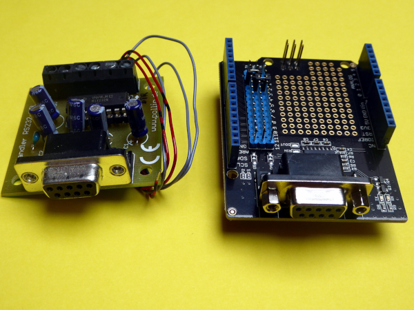
To create the TIA-232 signals, extra ICs with the marking 232 (e.g. MAX232) were developed. They have a circuit called charge pump or DC-DC converter, working with capacitors, to get higher voltages from 5 V or 3.3 V and to get the negative voltages. The signals are amplified with inverting amplifier. Here a circuit with the bigger MAX238 that allows also to use control or message lines:
A breakout board and an Arduino shield with MAX232:
Serial to USB
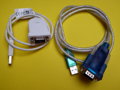
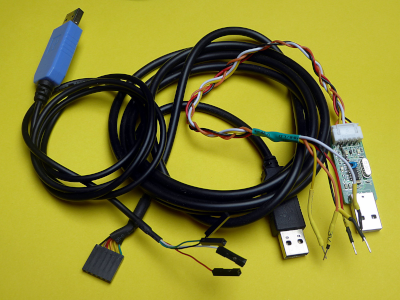
Today computers have seldom an external TIA-232 interface (even if it's available on most motherboards). So USB to TIA-232 adapters are used (left picture). We find them as breakout boards or cables often with only TxD and RxD, but they also exist with control lines.
If we work with microcontroller or single-board computers (e.g. Raspberry Pi) mostly only serial data lines are needed. So cables with TTL signals (5 V) or with 3.3 V signals can be bought (right picture). It is important to look at the voltage if we use 3.3 V microcontroller or the Raspberry Pi that uses also only 3.3 V on his GPIO's! 5 V data lines could destroy your chip.
We also get cables with a supplementary control line to program an AVR chip with Arduino (cable with 6 pol header).
There exist different chips, the most known are the chips from FTDI (best compatibility, e.g. FT232R), Profilic (e.g. PL2303) or WCH.cn (e.g CH340). In Linux the drivers are already integrated. In Windows or macOS they must be installed.
Bit rates and baud rates
Baud is the unit for the symbol rate (modulation rate) in symbols or better pulses (changes of the signal) per second. The symbol rate is called baud rate and is only one of the components that determine the speed of communication over a data channel. As it is possible to send more than one bit with one signal change, the bit rate (gross bit rate) in bits per second is normally not equivalent to the baud rate. Only in binary systems with only two symbols the baud rate and the bit rate are equivalent.
It is better to use only the bit rate to avoid confusion and wrong designations.
Bit rates used for TIA-232 are:
75, 110, 134.5, 150, 300, 600, 1200, 1800, 2400, 4800, 7200, 9600, 14400, 19200, 38400, 56000, 57600, 76800, 115200, 128000, 230400, 256000, 460800 bit/s.
Today the following bit rates are mostly used (especially the bold ones):
| speed in bit/s | data rate with 8N1 in byte/s (10 bit/character) |
|---|---|
| 1200 | 120 |
| 4800 | 480 |
9600 |
960 |
19200 |
1.875 |
| 38400 | 3.74 |
115200 |
11.25 |
The bit rate of hardware serial is derived by binary dividers from the clock of the microcontroller. Arduino AVR chips often use a crystal of 16 MHz. For certain bit rates the error of the rate gets above 1 %. This can be seen in the data sheet, or on this page. So, to get a good connection it is best to avoid 57600 bit/s and 115200 bit/s on Arduino and use 38400 bit/s instead (this does not count for the serial monitor which is emulated over USB).
"Just do it" TIA2:
Search and document the errors in the data sheet of ATmega328 for a crystal of 16 MHz (Arduino Uno R3) for the bit rates of 38400 bit/s, 57600 bit/s and 115200 bit/s. What bit rate of these three would suit best for serial operations? What crystal would suit best for serial operations?
Calculate the time needed to send a text file with 10.7 kibibyte over serial (8E1, 38400 bit/s).
Cable length
The possible cable length depends on the used voltage, the electromagnetic shielding of the cable and the capacitance of the cable (the lesser the better). A CAT7 network cable gives a bigger range than a CAT5 network cable. Here a table with RS232 cable length according to Texas Instruments (source wikipedia), to give an indication:
| bit rate in bit/s | max. length in m |
|---|---|
| 2400 | 900 |
| 4800 | 300 |
| 9600 | 152 |
| 19200 | 15 |
| 57600 | 5 |
| 115200 | <2 |
By halving the maximum communication speed, the allowed cable length increases a factor ten!
As the cables today are much better the ranges increase. The cables in the standard had a capacitance of about 170 pF/m. CAT5 cables have about 57 pF/m. This increases the length of the cable min. by a factor 3. With CAT7 we get much bigger lengths than in the table.
Serial data format
We have seen in the previous chapter that in a serial transmission the data is transferred bit by bit from the sender Tx to the receiver Rx over one data line. With the help of shift register the parallel data is converted to a serial stream. In asynchronous serial communication the sender and receiver have no common clock, so we need synchronisation information contained in the data stream. This is done in TIA-232 with a start bit at the beginning and stop information at the end of the stream.
With TIA-232, we get an on state known as mark and an off state named space. When the line is idle, it is kept in the mark state.
Data bits are sent with a predefined bit frequency (bit rate), that both the sender and receiver must know. After the first bit is received, the receiver calculates . It will check the line voltage levels at those moments.
Start bit
As there is no clock information, the receiver needs to resynchronise with the help of the start bit (signal going from mark to space, falling edge). After the received falling edge of the signal the receiver samples the line with a higher clock than the bit rate and tries to detect the centre of the start bit to know at which moments the other data bits will be received.
Data bits (5,6,7,8)
The first communication over serial worked with 5 or 6 bit in teletype times. To get 128 characters and control codes for ASCII, 7 bits and later 8 bits (256 character) were used. So it is possible to choose the number of data bits. Today normally 8 bit are used. Naturally sender and receiver must use the same amount of bits.
This is called little-endian (bit endianness).
Parity bit (E,O,N)
For simple error detecting, an extra bit was added to the data byte automatically by hardware. This parity bit can be even (E), odd or none. With even parity, for the whole data byte, the bits whose value is 1 are counted. If that count is odd, the parity bit is set to 1, making the total count of 1's in total (including the parity bit) an even number. Otherwise the parity bit is set to 0 to maintain the even number. In the case of odd parity, the coding is reversed.
Today the parity bit is very seldom used.
Stop bits (1, 1.5, 2)
The stop bit has mark value. With slow modems, 1 stop bit was sometimes not enough and so it was possible to send 1.5 or 2 stop bits, no more used today. As the receiver knows the bit rate, a missing stop bit is showing a synchronization failure (framing error) and the receiver can try to resynchronize on new incoming bits.
Today mostly 8 data bit, no parity and 1 stop bit called "
8N1" is used.Examples of serial data units
"Just do it" TIA3:
Find the ASCII characters sent in the both examples above.
In the chapter "voltage levels" we have the picture of an oscilloscope screen. Find the data format, the bit rate and the two characters sent.
Serial on Arduino
For information about serial on Arduino look at the Arduino reference here or at Paul J. Stoffregens homepage here. Paul rewrote and improved parts of the Arduino libraries to be used with the Teensy boards.
On microcontroller we can use a software emulated serial communication (a pin is switched on and off by a library (e.g. softserial on Arduino)), or use an integrated UART or USART for hardware serial. The UART (Universal Asynchronous Receiver-Transmitter) is a hardware part in the microcontroller that handles the asynchronous serial communication. The data format and transmission speeds are configurable through registers. Up to six UART or USART are commonly integrated in newer microcontroller chips. The USART (Universal Synchronous and Asynchronous Receiver-Transmitter) also supports synchronous operation.
If possible we always use hardware serial because it doesn't disturb our timing of the program and the data stream timing is much more accurate. Hardware serial mostly works with interrupts, so interrupting the main program only very shortly. They use a buffer to store the outgoing and incoming data.
To use hardware serial in Arduino the following line suffices:
Serial.begin(115200);
Serial is the serial port object and corresponds with Serial0. If more ports are available (Teensy, ESP8266, ESP32) they are called Serial1, Serial2 etc.. The used parameter (115200) is the bit rate. The default data format is 8N1 (8 data bits, no parity, one stop bit). This can be changed with an optional second parameter.
Often Serial is used for the Arduino serial terminal monitor. So if a real hardware serial port is needed it is best to choose a chip with a second serial port.
The commands to send data are Serial.print() and Serial.write().
Serial.write(value) sends the bit pattern of a one-byte value as is (binary data). Serial.write(string) sends the bit patterns of the characters of the string one by one. Serial.write(buffer, length) can be used to send the bytes of an array. Length defines how many bytes of the array will be sent. Serial.write() returns the number of bytes written.
- Hint: If the transmit buffer is full,
Serial.write()will not return (block) until there is enough space in the buffer. To avoid blocking is possible to check if there is enough free space in the transmit buffer with the methodavailableForWrite(). To clear the buffer from old data we can useSerial.flush().
Serial.print(value,format) or Serial.println(value,format) uses Serial.write() but converts the data first in a human-readable ASCII text. Characters and strings are not changed but e.g. numbers are printed using an ASCII character for each digit. With the second parameter format the base for the conversion can be specified. Allowed are BIN, OCT, HEX and DEC. For floating point numbers, format specifies the number of decimal places to use. Serial.print() also returns the number of bytes written.
As already seen flash-memory based strings can be send by wrapping them with F().
With Serial.read() we get serial data. The method returns the first byte of incoming serial data available as integer (-1 if no data is available). Normally it is used in combination with Serial.available().
Serial.available() returns the number of bytes available in the serial buffer. Sometimes, if we get big data chunks, it is necessary to increase the serial buffer size. This can be done in the serial header file (HardwareSerial.h) or with the method setRxBufferSize() if we use an ESP8266 or ESP32 chip.
  byte incoming_byte;
  while (Serial1.available() > 0) {  // if any serial available,
    incoming_byte = Serial1.read();  // read it and write it to the terminal
    Serial.write(incoming_byte);     // alt: Serial.write(Serial1.read());
  }
Hint: If you need to flush the input buffer, use the following code:
   void serial_in_flush() {
     while(Serial.available() > 0) {
       Serial.read();
     }
   }
Other methods are Serial.readBytes(),Serial.readBytesUntil(), Serial.readString() and Serial.readStringUntil().
Here a simple program to send and read a two bytes:
    // TIA_232_simple loopback with Teensy 2.0

    byte incoming_byte;

    void setup() {
      Serial.begin(115200);              // initialize serial for terminal
      delay(500);                        // mega32u4 needs a little time
      Serial1.begin(115200);             // initialize hardware serial
      Serial.println("Test begins");
    }

    void loop() {
      Serial1.write("Gu");               // write two bytes
      while (Serial1.available() > 0) {  // if any serial available, read it
        incoming_byte = Serial1.read();  // and write it to the terminal
        Serial.write(incoming_byte);     // alt: Serial.write(Serial1.read());
      }
      Serial.println();
      delayMicroseconds(200);
    }
"Just do it" TIA4:
- Let's test the program from above. We connect
TxD(PD3) from Teensy 2.0 directly toRxD(PD2) with a cable. This is called a loopback test. Measure the signal with the help of an oscilloscope. Print the screen and mark in the picture the start bytes, data bytes and stop bytes. Analyse the data bytes (ASCII table).
"Just do it" TIA5:
For this excercise we use a GPS-module GT-U7 from Goouuu Tech that is NMEA compatible. The chip on the module is a
NEO-6M, that works with 3 V. The module itself is powered with 5 V. The chip sends his data through a serial interface (3 V).
We will connect the module to our MH-ET Live ESP32. The ESP32 has three UART.UART0(Serial) is used for programming and for the serial monitor.UART2(Serial2) is available on the GPIO pins16(RxD2) and17(TxD2).UART1(Serial1) is connected to GPIO 9 and 10, but these are not available because they are connected to the integrated SPI flash. Fortunately ESP32 has multiplexing features, and so pins can be changed in code. This can be done with the begin command:Serial1.begin(9600,SERIAL_8N1, 21, 22);With this command we define GPIO pin
21forRxD1and pin22forTxD1.
Search in your Arduino installation folder (Linux: /Arduino/hardware/espressif/esp32/ or /portable/packages/esp32/, Win10: C:\Users\xxx\AppData\Local\Arduino15\packages\esp32\hardware\esp32\1.0.4\cores\esp32 (enable hidden files)) for the three filesHardwareSerial.h,HardwareSerial.cppandesp32-hal-uart.h.
Describe all the parameters of the.begin()method. How are the default pins defined?Connect the GPS-module GT-U7 (9600 bit/s, 8N1) to
Serial1and send the data to the Serial monitor and as a stream with 115200 bit/s overSerial2. As we don't catch all the characters, it is necessary to set a bigger RX buffer with the methodsetRxBufferSize(). Set the size to 512 byte.
Document the program , the serial monitor output and document theSerial2output with an oscilloscope screen.
Tip: The antenna needs to see some satellites, so place your circuit near a window.NMEA sentences start with the
$character, and each data field is separated by a comma. The most interesting information is the line beginning with$GPGGA. It provides the basic GPS NMEA information with 3D location and accuracy data. Research the information of the first line and send it in a good readable format over both serial (e.g. "The time is ...\n", "The latitude is ...\n`).Next we want to send the decoded stream with the help of a
MAX232to a PC. Look at the data sheet for the circuit to be built. What has to be done because of the different voltage levels (5 V, 3.3 V)? Draw the circuit in e.g. Frizzing and build it on a breadboard. Document theMAX232output with an oscilloscope screen.Use a serial to USB cable and a terminal program like
cutecomorclevertermto read the data on a PC screen. Dokument the screen.
"Just do it" TIA6:
As seen
TIA-485specifies only electrical parameters and the protocol used is often based that of TIA-232. We will now send our GPS information from one microcontroller to another (Teensy 2.0) and use TIA-485 to do it. The result will be seen on the serial monitor from Teensy 2.0. We will use two MAX490 (data sheet) to built the circuit. Draw the circuit (don't forget to insert a terminating resistor).Test your connection with a bit rate of 1 Mbit/s. Document the program and the oscilloscope screen.
"Just do it" TIA7:
Modbusis a serial communications protocol and a de facto standard communication protocol for industrial devices.M-Busis a European standard for the remote reading of meters (water, gas or electricity). Compare both buses withTIA232.What would we need to connect one of our microcontroller as device (slave) to Modbus respectively M-Bus?
Interesting links
- https://www.arduino.cc/reference/en/language/functions/communication/serial/
- https://www.pjrc.com/teensy/td_uart.html
