CNC
Plotting, lasering, and milling with Inkscape
last updated: 02/04/20
Getting Gcode using Inkscape
For my first tests, I want to draw something with the help of a pen. I like Inkscape a free and open source vector drawing program. The extensions for Inkscape are really cool and I use them e.g. for my egg-bot. The extension Gcodetools generates Gcode for Lasercutter/Engraver or Plotter. Unfortunately it is not well documented (look here).
Because of the bad documentation and the unpredictable results, using Inkscape to generate G-code for CNC mills is dangerous! Better use more professional software.
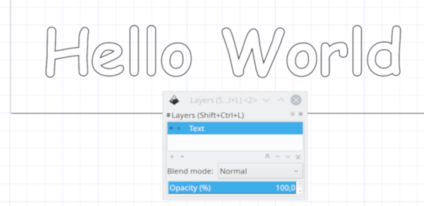
Let's try to write Hello World with the CNC machine used as plotter. In Inkscape we select the text tool and write the text in Comic Sans MF, bold, size 72. As we need the outline, add a stroke paint (shift + click on black color in the palette bar). Delete the fill (click on cross in palette bar).
Next we scale the object to 100 mm in width and 10 mm from x and y:

The object needs to be in an own layer. Create a layer called "Text" and put it there (right click, move to layer...).

As we need a vector graphic and not a text object, we duplicate the layer (right click: Duplicate Current Layer) and get a Layer with the name "Text copy". Now we toggle the visibility of the "Text" layer to invisible. It is only needed again if we want to change the text. In the "Text copy" layer we select the text and use Path > Object to Path to get a vector graphic.
To avoid that the G-code generation freezes up or takes too long, we want to have less than 3000 nodes. If we have too many nodes, we can simplify the object by pressing ctrl+L as many times as necessary. The node count is showed in the status bar. As our text has less than 3000 nodes, so we don’t have to simplify.
Now we we need to choose a tool. Click on Extensions > Gcodetools > Tools library…. For our need (laser engraver and plotter) we choose the cylinder option and than click on Apply.
A green text box pops up in our drawing. We close the "Tools Library" window and position the green box above our drawing. The box is part of the image with the text tool we adjust the parameters. We set the tool diameter to 1, the feed rate to 400 mm/min and penetration feed to 10000 (arbitrary high number to quickly turn on and off the laser).
Next we need some orientation points. Select Extensions > Gcodetools > Orientation points….
will be continued in short
