CNC
Milling with bCNC
last updated: 06/04/20
Introduction
As stated on the github page from Vasilis Vlachoudis bCNC is a GRBL CNC command sender, auto-leveler, g-code editor, digitizer, CAM and Swiss army knife for all your CNC needs.
bCNC is written in python and so runs on Linux, Mac and even Windows :). I use here the most recent version 9.14-dev.
An important page for information is the bCNC Wiki.
As a memo I enumerate already here the different work steps needed to mill a piece in bCNC. The steps are explained in detail in the following project.
Work steps in bCNC
- Open the file and place it on the workspace (
Editor). - Rename and rearrange the gcode blocks (
Order > Optimize). - Define and add the cutter (diameter), the material (feed rate and depth increment) and the stock (thickness) in the
CAMwindow. - Define the cutting profiles (
Profileicon inCAM) for the different blocks (have to be marked inEditor, choose inside resp. outside). Click on theProfilebutton. - Mark all the cutting lines in the
Editor, go back theCAMtab and click on theCuticon. Choose a ramp and a ramp length. Click on theCutbutton! - To add
Tabswe mark one or more blocks (Editor) an click on theTabsicon (CAM). Choose the number of tabs, the width and the height (counted from the surface of the working piece (Z = 0): height of standing material - thickness work piece = negative value). Click theTabsbutton. - Position your cutter and click on
XYZ=0in theControltab. Click onStart:).
Install bCNC
Download bCNC from https://github.com/vlachoudis/bCNC and extract the zipped file. Read on git how to install it. On my Kubuntu I chose not to install it but changed to the bCNC subdirectory and started the program with
./bCNC
(If tkinter is missing you can install it with sudo apt install python-tk).
Configure bCNC
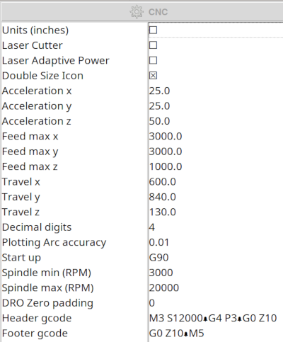
First I needed to customize the program because of it's tiny icons and font size. In the CAM tab there is a Config icon, displaying the Machine configuration for bCNC parameter. Here we find a checkbox to double the icon size.
Other important settings are:
- units unchecked (for mm)
- feedmax xyz (3000,3000,1000 for stepcraft D)
- travel xyz: These values define the work area e.g. 600,840,130 (yellow rectangle)
- Spindle min/max e.g. 3000,20000
The other settings can remain with the default values.
More infos about the configuration parameter can be found on github
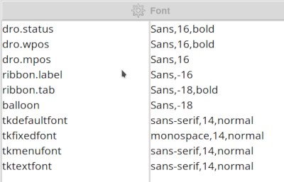
The Fonts icon helps to get a bigger font.
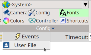
For more config parameter you can edit the User File, normally locatet in the home directory under .bCNC.
Changing GRBL parameter with bCNC
Tweaking the different GRBL parameter for a milling machine can be done with a terminal program, but it is much more comfortable to use a GUI program like bCNC.
Click on the Controller icon. The following parameter have to be changed for a Stepcraft D840 mil. The other parameters stay on default values. For more informations on the parameter for your machine you can look in the GRBL wiki.
$5 Limit pins invert: The STEPCRAFT limit switches are normally closed (NC), expects normally open (NO), so we have to invert. Click the checkbox!$6 Probe pin invert: Also normally closed (NC). Click the checkbox!$21 Hard limits: We use them, so click the checkbox!$22 Homing cycle: We need homing. Click the checkbox!$23 Homing direction invert: The X axis needs to change the direction for homing. This is done with the number 1. Change zero to1.$27 Homing pull-off [mm]: This is the distance to the limit switches after homing. I increased it to 3 mm.$30 Max spindle speed [RPM]:20000for the STEPCRAFT spindle.$31 Min spindle speed [RPM]:3000for the STEPCRAFT spindle.$100 X steps/mm:133.33for the STEPCRAFT motors (4003 steps/3 mm pitch of the trapezoidal thread spindles).$101 Y steps/mm:133.33for the STEPCRAFT motors.$102 Z steps/mm:133.33for the STEPCRAFT motors.$110 X max rate [mm/sec]:3000for the STEPCRAFT machine.$111 Y max rate [mm/sec]:3000for the STEPCRAFT machine.$112 Z max rate [mm/sec]:1000for the STEPCRAFT machine.$130 X max travel [mm]:600for the STEPCRAFT machine.$131 Y max travel [mm]:836for the STEPCRAFT machine.$132 Z max travel [mm]:130for the STEPCRAFT machine.
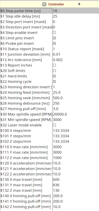
After changing the parameter you have to click on Controller to upload the data to GRBL.
Waving Makey: a first little project
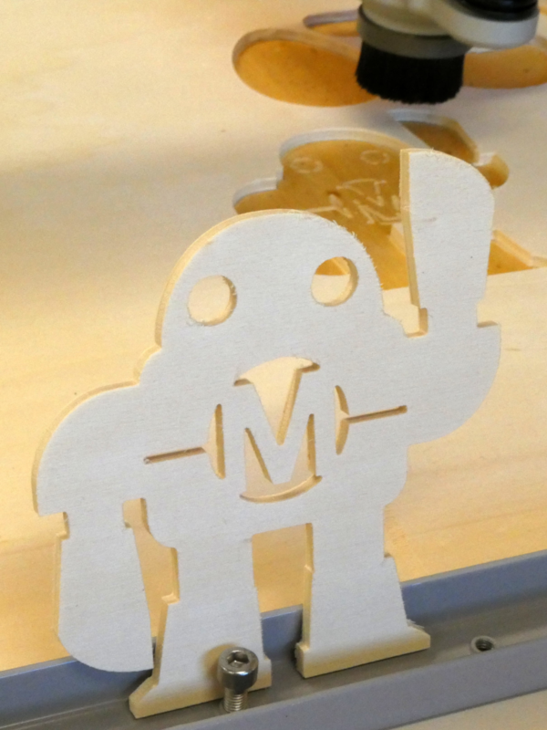
I want to use the waving Makey from adafruit. I eliminated the gaps in Inkscape, used the union function to get one object and finally converted the object to a path. Find the file at the bottom of the page.
Now we open the file in bCNC. In the Editor tab we move the drawing into our workspace (yellow rectangle) using the move icon. It is also a good idea to rename the different gcode blocks (subprograms) and perhaps to change their order to get a better workflow (outline to the end). The express rides of the tools can be enhanced further with the optimize function in the subtab Order. Select all the hole blocks and use this function.
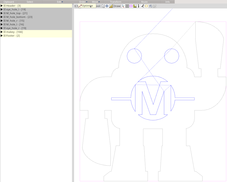
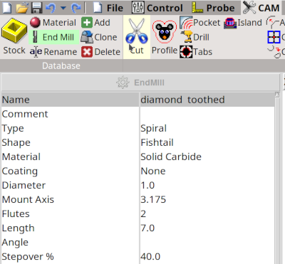
The next steps are to define the cutter, the material and the stock. We will add these to the database of bCNC. Click on End Mill in the CAM tab and then on the Add button. This adds your tool to the database (saved in ~/.bCNC). The most important setting is the diameter. I will use a 1 mm spiral diamond toothed cutter.
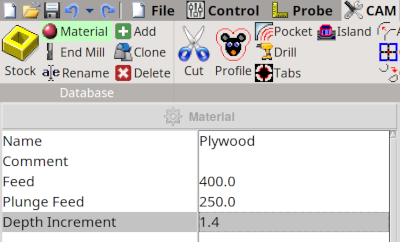
In the material window (Material + Add) we add our material (plywood birch) and choose the feed rate (see feed_rates), the plunge feed (z-axes speed) and the depth increment.
As I use 4 mm plywood (poplar or birch) for this project I can calculate the feed rate approximately from the material and the used cutter. The calculations are shown here: http://www.weigu.lu/other_projects/cnc/feed_rates/index.html. A rule of thumb says that the maximum increment of depth for cutting is the double of the cutter diameter. Here we chose 4/3 = 1.4 mm, so the job is done in 3 passes.
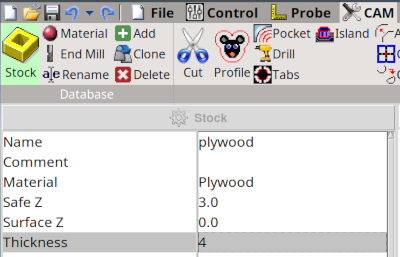
The stock window (Stock + Add) is needed to define the safe Z distance for moving above the stock and the thickness of the stock.
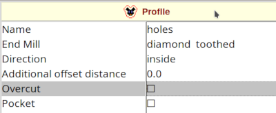
Now we define the cutting profile. Mark all hole blocks in the Editor tab and then click on Profile in the CAM tab. Choose inside and click on the Profile button above the window.
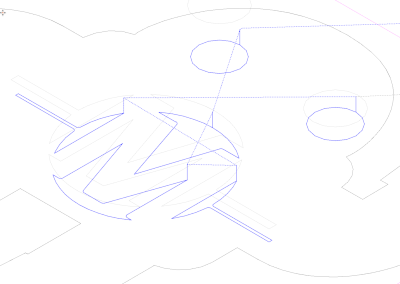
After this we see the blue cutting lines lying inside the outline lines.
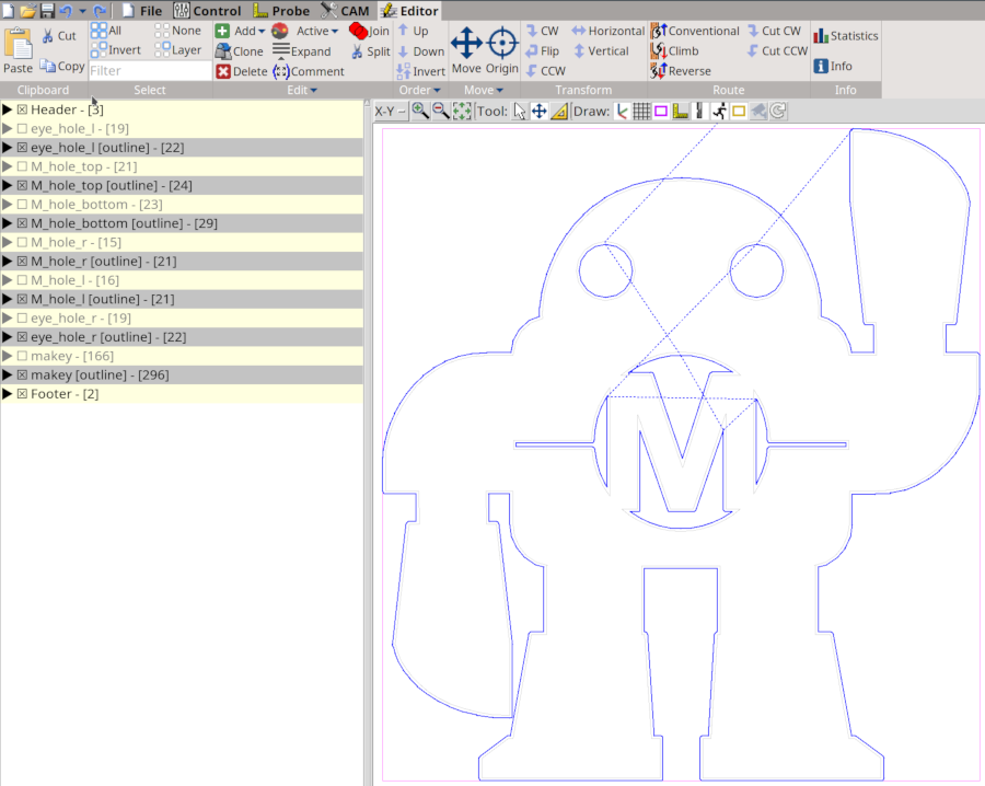
Then mark the outline block (Editor), switch back to Profile (CAM), choose outside in the Profile window and click a second time on the Profile button.
The blue cutting lines of the Makey outline lie outside our project.
Mark all the cutting lines in the Editor, go back the CAM tab and click on the Cut icon. Here we choose a ramp as cutting strategy with a ramp length of 2 mm.
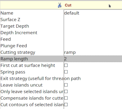
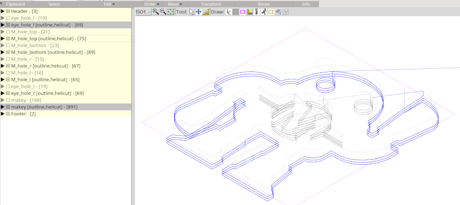
Click on the Cut button! In the isometric view we now see the cutting path.
Adding Tabs
If you don't have a vacuum table, it is important to add "Tabs". They will be left uncut to hold the part in place after cutting. This prevents the user from being hurt by projectiles and the braking of the thin cutter. In bCNC (>1.11) tabs are round.
To add Tabs we mark one or more blocks of gcode in the Editor. In the CAM tab click on the Tabs icon.
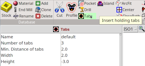
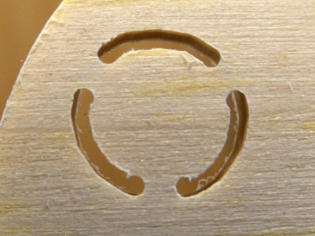
Depending on the dimensions of the cutting part we choose the number of tabs and the width of the tabs. For the Makey eyes e.g. I choose 3 tabs (Number of tabs) with 2 mm in diameter (Width), for the outline 6 tabs with 5 mm. The Height is counted from the surface of the working piece (Z = 0), so it has to be negative. For an 1 mm tab in a working piece of 4 mm we need to set the Height to -3 mm (better choose 1.5 mm!)
Click the Tabs button. Now you see the tabs (located on Z = 0)!
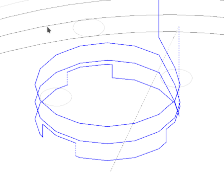
To modify the cutting path we need to cut the tabs from the path. Open the Cut window. It's important to check the Leave islands uncut box in the Cut window. Now click on the Cut button. The result for an Makey eye should look like the following image:

Position your cutter and click on XYZ=0 in the Control tab. Click on Start :).
Consolidate: A stand for Makey
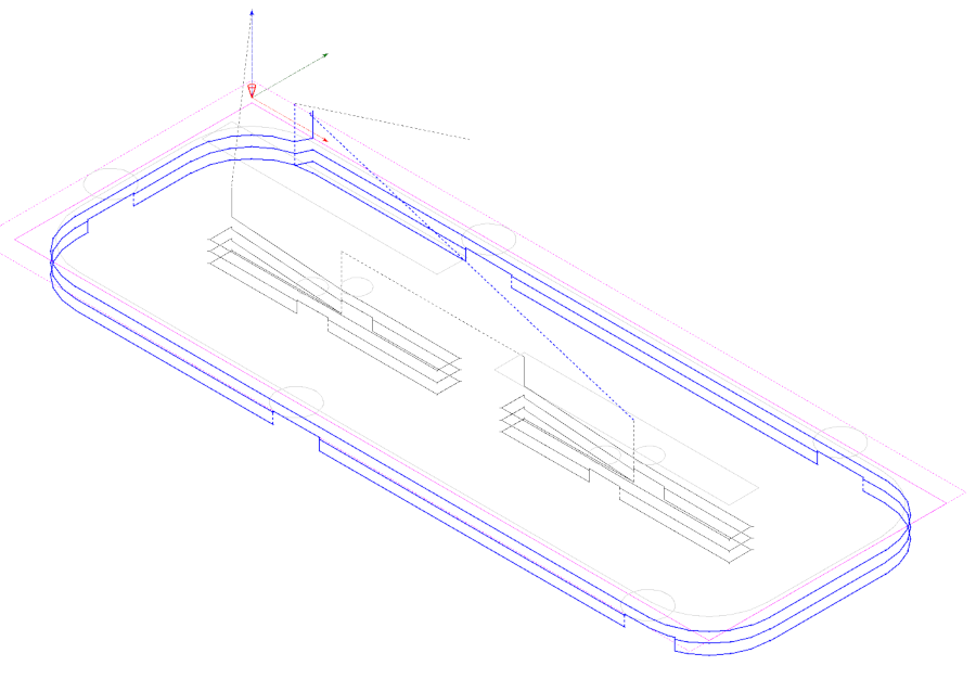
Get the Incscape file (Downloads) for the stand an repeat the different steps from above. Use an overcut for the two holes (in the Profile window).
Downloads
