Tutorials: Electronics fundamentals (ELEFU)
Diode D and Transistor T
last updated: 2022-010-12
Quick links
Introduction
Song of this chapter: Aerosmith > Aerosmith > One way street
After the discovery of rectifying properties and the Edison effect, and the development of diodes (both vacuum-tube and semiconductor) and triodes (vacuum-tube), it was possible to get a DC voltage and current from an AC source, and to build radio receiver detectors and amplifiers like the crystal detector used in early 20th century radio receivers.
In the midst of the 20 century semiconductor diodes and transistors based on germanium and silicon replaced the vacuum tubes, consuming less energy and volume. Now it was possible to produce portable electronic devices. Today most diodes and transistors are based on silicon, but germanium and gallium arsenide are also used.
Beginning in the 1970s, more and more transistors were connected on a single chip (integrated circuits IC or chip). With this began the transistor count in IC's.
Diode (wiki)
Song of this chapter: Aerosmith > Aerosmith > One way street
Diodes are non-linear components and they are always polarized!
They let current flow in only one direction! For this they have to be forward-biased, meaning there is a positive potential on one terminal, called anode and a negative potential on the other terminal called cathode. The potential difference must be greater than approximately 0.7 V for silicon diodes (0.3 V for germanium diodes and 0.2 V for Schottky diodes).

Water analogy
In the water analogy we have a one-way valve. A spring shows that we need a certain pressure (voltage) to open the door if the water flow is in forward direction.

Diodes symbols and models
Symbol of a diode, a light emitting diode (LED) and a Zener diode (Z-diode):


The symbol clearly shows the forward direction with an arrow. The cathode is shown with a line. In cylindrical housings we have a ring showing the cathode, on surface mount diodes (SMD) it's a line.
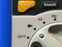
Standard LED's have often a longer leg indicating the anode pin or a flat edge on the LED’s outer casing showing the cathode pin. An easy way is also to use the diode function on a multi-meter to test for polarity (see later).

Diode forward-biased and reverse-biased
At a greater voltage than 0.7 V the resistance of a silicon diode will get very low. With no limit for the current, the diode will eventually melt from the heat generated. So we have to include some other limiting component (e.g. resistor) to the circuit.

p-n junction (wiki)
Silicon is basically found in sand and it's the the eighth most common element in the universe by mass. In it's pure form it's a hard and brittle crystalline solid. At -273 °C it's an insulator. But at 20 °C (+293K) we get a semiconductor because bonds in the crystal are breaking and we get free electrons.
By adding impurities to the pure silicon, different properties can be realized. Doping silicon with per example phosphorus introduces extra electrons. We get an n-type semiconductor that has extra electrons that can wander around the crystalline structure of the silicon. Doping silicon with per example boron creates a p-type semiconductor with missing electrons (holes) to complete the crystalline bonds.
Joining n-type silicon to p-type silicon creates a p-n junction. This p-n junction acts as a diode, or if the dimensions and doping are right as a photo cell.

The junction between the types creates a barrier to the electrons and holes (because they are recombining we get an insulating zone), the depletion zone. In forward-bias direction a positive voltage on the anode (p-type), pulls the electrons to the junction and a negative voltage on the cathode (n-type) the holes. The depletion zone gets smaller. When the voltage difference is big enough the depletion zone disappears. The current can flow freely across the junction.
Reverse-biasing the p-n junction only widens the depletion zone. If the reverse-bias voltage difference is too high, the junction will heat up and we get an electrical_breakdown. This can destroy the p-n-junction.
Circuit example: AND and OR gates with diodes
In the last decades electronics moved dramatically from analogue to digital. Two elementary digital circuits are the OR gate and the AND gate. We will use the positive logic, so the two digital states true and false will be represented with HIGH (1, +5V or +3.3V) and LOW (0, 0V). Two inputs for the gate will give 2² = 4 possibilities or cases (3 inputs would give 2³ = 8 cases).
Logic OR
Logic OR is only false if none of the conditions are fulfilled. If I drink water OR lemonade I won't be thirsty any more. It's not an exclusive OR because I can also drink both drinks, even mixed :). This gives us the following truth table:
| case | B | A | Z | case | B | A | Z | |
|---|---|---|---|---|---|---|---|---|
| 1 | false | false | false | 1 | 0 | 0 | 0 | |
| 2 | false | true | true | 2 | 0 | 1 | 1 | |
| 3 | true | false | true | 3 | 1 | 0 | 1 | |
| 4 | true | true | true | 4 | 1 | 1 | 1 |
Logic AND
Logic AND is only true if both conditions are fulfilled. If I have money AND my girlfriend has time we will go to the cinema.
| case | B | A | Z | case | B | A | Z | |
|---|---|---|---|---|---|---|---|---|
| 1 | false | false | false | 1 | 0 | 0 | 0 | |
| 2 | false | true | false | 2 | 0 | 1 | 0 | |
| 3 | true | false | false | 3 | 1 | 0 | 0 | |
| 4 | true | true | true | 4 | 1 | 1 | 1 |
"Just do it" D1:
- We will use diodes to build an
ORgate and anANDgate. The output will be visualized with a light emitting diode. Build the first circuit and document all 4 states by drawing the 4 circuits with their corresponding measured potentials and currents. Explain in detail how the circuit is working.


- Build the second circuit and document all 4 states by drawing the 4 circuits with their corresponding measured potentials and currents. Explain in detail how the circuit is working.
Diode characteristics
Do you remember the last exercise in the second chapter (Ohm's law)? We measured the I-U-diagram of three different resistors and of our diode 1N4148.
The resistor has a linear characteristic! You can see in the I=f(U) diagram that when the voltage is doubled the corresponding current doubles. This is true for both directions, as the resistor is not polarized. Here is the straight from a resistor (1kΩ) in a complete diagram. In fact we combine two diagrams, one in forward-bias and one reverse-bias.

Let's look at the diagram of a diode 1N4148. The 1N4148 is a standard silicon small signal fast switching diode. It's very often used in circuits, because of it's switching capabilities up to about 100 MHz. Because of it's popularity there are more than one manufacturer and also slightly different data-sheets.
Both diagrams are non-linear. Watch for the axis, they are not the same!! The diode is used in forward direction. Reverse biased it will break down (it will be destroyed) at 75 - 100 V.

Between the two knees of the curve (UF and UBR) the current is practically zero. If the voltage gets higher than UF = 0.7 V the diode is getting conductive and the current is very soon reaching it's maximum (about 200 mA). That's why we need a another component in series (resistor) to limit the current and prevent the diode from being destroyed.
The other knee of the curve shows at witch voltage the diode breaks down (is also destroyed except for Zener diodes (see later)). This happens at UBR = 75 V-100 V.
"Just do it" D2:
- Look at the absolute maximum ratings in the data sheet of the diode 1N4148 and compare with our diagram. Also look at the diagrams in the data sheet. What are your findings?
Tip: There are more than one manufacturer and so also different data sheets. Search for the best data sheet suited. - How does the temperature affects the curves of a diode?
- The forward voltage of a silicon diode lies between 0.5 V and 1 V. It can be measured approximately with a multi-meter. Measure the resistance of a diode 1N4148 in forward- and reverse-bias (select the range manually!) and measure the forward voltage with the multi-meter.
As our characteristic curve is non-linear, it is difficult to calculate the currents and voltages in a circuit. Also the real curve may differ from the curve in our data sheet. A simple possibility is to measure the curve, draw a diagram and read the working point of the circuit from that diagram.
Here is an example for a diode 1N4148 in series with a resistor. The curve from the resistor is mirrored to get the working point of the circuit. Point 1 to draw the straight of the resistor is on the current axes an is calculated with the total voltage of the circuit and the resistance of the resistor IP1 = U/R. Point 2 is the total voltage on the voltage axis. The intersection of the two curves (working point delivers the results (UD,UR and I).


"Just do it" D3:
- It's a long way back that we didn't look at our rover. We soldered a diode 1N4004 or 1N4007 to the PCB. What is the difference between these two diodes?
- Use a power supply and measure enough points to draw the diode curve (I = f(U)) in forward direction (max. 1 A!). Draw the measurement circuit by hand. Draw the diode diagram.
- The motors take the 6 V directly from the batteries. Our PCB needs only 5 V. Measure the voltage before an behind the diode (switch closed). Calculate the resistance of the whole PCB if it takes 180 mA. Now get the working point of our circuit with the graphic method from above.

Rectifier (wiki)
Diodes are used to produce with the help of capacitors a DC voltage from an AC source.
"Just do it" D4:
Test the following circuit. The circuit is called a half-wave rectifier. Either the positive or negative half of the AC wave is passed, while the other half is blocked. Document the output voltage and the voltage on the diode (Math function!).

What does the current look like? Calculate the peak current.
We get a pulsating direct current. With the help of a big capacitor we can filter the AC frequency from the output and plane the voltage. Add a capacitor of 4700 µF (16 V) in parallel to the output. Document the output voltage with the oscilloscope.
"Just do it" D5:
- A better circuit is the full-wave rectifier. Document the output voltage with the oscilloscope (use the Math function!). Describe the output signal. What can we say about the frequency of the output signal?

- Explain the circuit.
- We get also a pulsating direct current. Add a capacitor of 4700 µF in parallel to the output. Document the voltage with the oscilloscope. Comment the result.
- Find a formula
URMS = f(Upeak).
The arrangement of four diodes is called a diode bridge or a Graetz bridge, and is often used in a single four-terminal component.

Types of diode.
Signal diodes
Meant for low voltage and low current use. See our 1N4148 signal diode. They often have a small glass case.
Power diodes
They can handle higher currents and are used per example for rectification in power supplies. Power diodes are larger and typically in heavy plastic or metal bodies.
Zener diodes (wiki)
Zener diodes have a quite precise breakdown voltage. Zener diodes are available with a large number of different breakdown voltages. You can use a reverse-biased Zener diode in series with a current-limiting resistor (acting like a constant current source) to regulate a voltage to the Zener (breakdown) voltage.
Light-emitting diodes LED's(wiki)
Light-emitting diodes are perhaps the best known diodes. LED's emit light (visible or otherwise) when forward-biased. The semiconductor material and the exact impurities used to create the p-n-junction determine the wavelength of the light (color). This also determines the forward voltage. This can vary from 1,6 V (red) to 4 V (white). The breakdown voltage of LED's is not very high, so pay attention if using LED's in AC circuits. Brightness of LED's can easily be changed with a PWM. High-power LED's (for illumination) are best driven with a current source circuit to achieve correct current regulation (see LED circuit).
Photodiodes (wiki)
Photodiodes will get conductive when enough photons (light) reaches the p-n-junction. The materials used to create the p-n-junction will determine at what range of the spectrum the diode is sensitive to.
Other interesting diodes are among others Laser diodes, Schottky diodes, variable capacitance diodes named Varicap and Gunn diodes.
Applications
The electricity available at our mains outlet is AC 230 V/50 Hz (URMS). Most electronic devices need a DC voltage from 3.3 V-24 V. Power rectification diodes in combination with transformers, capacitors and regulation circuits allow us to power electronic circuits from mains outlets.
When the power is turned off from inductors (electromagnets, solenoids, motors) they induce a reverse current that can generate a very high voltage. A diode is used to drain that current off and reduce that voltage, so the controlling circuit (typically a transistor) will not be destroyed. This is called "back EMF protection" and the used diodes "flyback diode".
Diodes are protecting circuits from connecting power with incorrect polarity (e.g.batteries). This reverse polarity protection can be done with one single diode in series to the circuit.
If you want make sure that a signal never exceeds a certain voltage, diodes can be used as a voltage clamp (or clamper).
"Just do it" D6:
- To repeat and consolidate this chapter, read the article about the diode in the HackSpace Magazine (free pdf download) number 12 (page 72-77).
Transistor (wiki)
Song of this chapter: Darren Korb > Transistor (original Soundtrack of the game)
In the year 1947 three researchers at Bell Labs invented the "transistor" (from "transresistance"). Before this fragile, big and power-hungry vacuum tubes were used for signal amplification and switching. Without the transistor the revolution in electronics and more specific in digital electronics that took place would not have been possible.
Transistors have three terminals. One terminal is used to control with a small current or a voltage a large current flowing between two other terminals. This makes the device capable of amplification or switching.
In this course we will only look at the transistor as switch.
Transistors symbols and models
There are two types of transistors: Bipolar Junction Transistors (BJT), and Field-Effect Transistors (FET). The FET's can be divides in two groups, the Junction Field-Effect Transistor (JFET) and the Metal-Oxide-Semiconductor Field-Effect Transistor (MOSFET).
Some symbols of different transistors:
Bipolar Junction Transistor (BJT) NPN, BJT PNP and Junction Field Effect Transistor (JFET) depletion type N-channel


Metal-Oxide-Semiconducter FET (MOSFET) enhancment type N-channel 4 terminal, MOSFET depletion type P-channel without substrate and MOSFET enhancment type N-channel subtrate connected internally with gate


Bipolar Junction Transistors (BJT) (wiki)
Bipolar junction transistor (BJT) use electrons and electron holes as charge carriers (unipolar transistor (e.g. FET) use only one kind of charge carrier).
As seen above, joining n-type silicon to p-type silicon creates a p-n junction. This p-n junction acts as a diode. BJT use two junctions between two semiconductor types, n-type and p-type, which are regions in a single crystal of material.
They exist as NPN and PNP types. The e.g. p-doped region in the middle for the NPN transistor is very thin to make the transistor work. So it is not possible to build a transistor with 2 diodes.
The three terminals are called Base, Collector and Emitter. The base current is controlling the main current from Collector to Emitter (resp. Emitter to Collector).

Water analogy
The water analogy can help to understand how a BJT is working:
Field-Effect Transistor (FET) (wiki)
The field-effect transistor (FET) uses an electric field to control the flow of current.
The terminals for the FET are called: Gate, Source and Drain. The gate voltage controls the current. In limits we can look at the FET as a voltage controlled resistor.
Field effect transistors have a very high input impedance at low frequencies. The most widely used field-effect transistor is the Metal-Oxide-Semiconductor Field-Effect Transistor (MOSFET or IGFET).

Transistor as a switch
In micro-controller circuits we often have to switch bigger loads than the controller can manage. Classical Arduino chips (ATmega328 or ATmega32u4) can deliver up to 40 mA per pin, ESP32 only 12 mA. Also the voltage that's needed by relays, motors, lamps etc. is not always 3.3 V or 5 V.
With transistors this problem can easily be managed.
NPN BJT
Let's begin with an NPN BJT. It's important to choose the right voltages and currents for the transistor, so we have always to study the data sheet.
The circuit itself is quite simple:

"Just do it" T1:
- We have a transistor BC546B. Compare the main voltages and currents with the BC547C. Note the differences. Does the circuit needs to be changed?
- Build the circuit and test it with the classical Arduino "Blink" program (
Files > Examples > 01. Basics). Calculate the collector currentICwhen the forward voltage of the LED is 1.7 V (UCE from data sheet). Measure the currentIC, the voltage on R2UR2, on the LEDUDand on the transistorUCE.
N-Channel MOSFET
Now we do the same thing with a N-Channel MOSFET 2N7000:

"Just do it" T2:
- Build the circuit and test it with the classical Arduino "Blink" program (Files > Examples > 01. Basics). Theoretically the resistors R1 and R3 are not needed. Explain their functions.
- Instead of one LED we want to use 5 similar LED's in series. Calculate the series resistor. Build and test the circuit. Measure the current ID, the voltage on R2, on the LED's and on the transistor UDS.
"Just do it" T3:
- In our Arduino set we have a relay breakout board. Reverse engineer the board and draw the circuit.
- Explain the function of the diode parallel to the coil.

H-bridge (wiki)
If we need to change the direction from a current through a device, we can use 4 transistor forming a H-bridge (so called because of the shape).
Here an example where the H-bridge is used to change the direction of a motor:
"Just do it" T4:
- We use an IC with two integrated H-bridges and integrated flyback diodes in our rover. Write an Arduino program to drive the motors for 5 seconds in each direction at full speed.

- Next we use a PWM to change the speed. Analyze the Arduino program from the rover chapter and strip it to the strict necessary (no access point) to let the motors run at 3 different speeds in two directions.
"Just do it" T5:
- To repeat and consolidate this chapter, read the article about the diode in the HackSpace Magazine (free pdf download) number 13 (page 62-67) and 14 (page 78-81).
Interesting links:
- https://www.electronics-tutorials.ws/transistor/tran_1.html
- https://www.electronics-tutorials.ws/diode/diode_1.html
- https://learn.sparkfun.com/tutorials/transistors/all
- https://https://en.wikipedia.org/wiki/2N7000
- https://https://en.wikipedia.org/wiki/BC548
