Single board computer projects
LAM NASA OSR: Reactivating the JPL NASA Open Source Rover
last updated: 2025-10-22
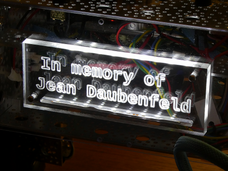
This page is dedicated to my dear friend Jean Daubenfeld.
He was a teacher at the Lycée des Arts et Métiers and worked until his last days on this rover.
He died on 28 October 2024 from a merciless illness.
Quick links
- Intro
- If you take the rover to the next Makerfaire
- Hardware
- Serial communication
- Bluetooth communication
- The main software (Python)
- The display software (Arduino)
- Downloads
- Interesting links
Intro
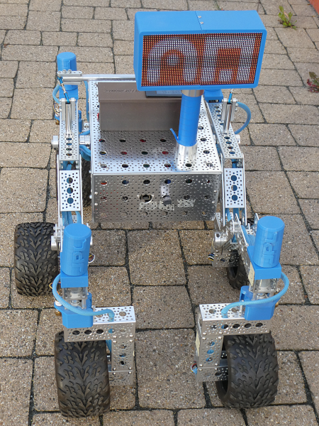
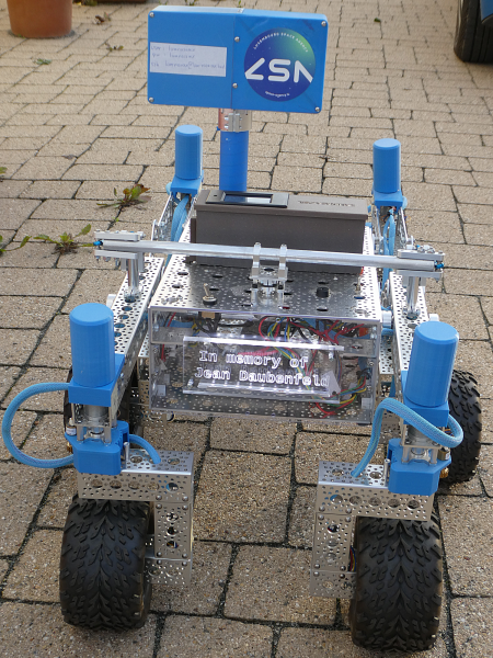
Here I gather infos on the update of our JPL NASA OSR. On the JPL github page we find two repos. One for the hardware and one for the software. Our Rover was build in 2018/2019 and 2019/2020 by students. The software did not work (ROS1). In 2021 we changed the PCB because of many broken wires in the old OSR.
The JPL robot and the software had many changes in the last 3 years. In the hardware git repo we find an older revF branch. We have PCB rev_E so it is easier to look at the Tags. Our updated rover model is v3.0.0. In the software git repo we have an older branch melodic-devel and a branch in between called v2-humble.
This version works without ROS.
If your interested. More information about ROS2:
https://www.weigu.lu/sb-computer/ros2_basics/ros2_jpl_nasa_osr/index.html
https://www.weigu.lu/sb-computer/ros2_basics/index.html.
If you take the rover to the next Makerfaire
- Get a second charged LiPo battery and a 2 new AA alkaline batteries (Xbox controller) as replacement.
- Don't forget the Imax B6AC battery charger and the Xbox controller.
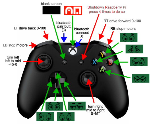
- Press the big X Button in the middle of the xbox controller for three seconds (it starts blinking).
- Switch the rover on and wait until the eyes of the rover blink!
- Have fun!
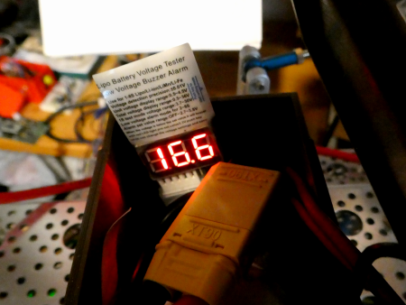
- If you replace the main battery don't forget to add the a low voltage buzzer alarm to the balancer connector of the battery!
Hardware
A first diagram shows the power distribution:
A second diagram the communication between the devices:
Raspberry Pi 4
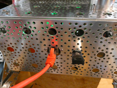
We use Raspi OS 64 bit with GUI and VNC (2025-10-01). To program the Raspi we use an RJ45 cable network connection (picture below). VNC is enabled for easier access. The Raspberry Pi communicates via his hardware serial port with the RoboClaw motor controllers.
An USB to Serial adapter talks with the Teensy microcontroller that controls the matrix. A USB Bluetooth adapter outside the rover body is used for stable Bluetooth connection to the XBox controller. The net tells that the internal bluetooth chip is not reliable.
Battery
We use Tattu RC battery LiPo with a capacity of 6750 mAh (14.8 V, 25C). The battery has an XT90 power connector and an JST-XH balancer cable to safely load the battery.
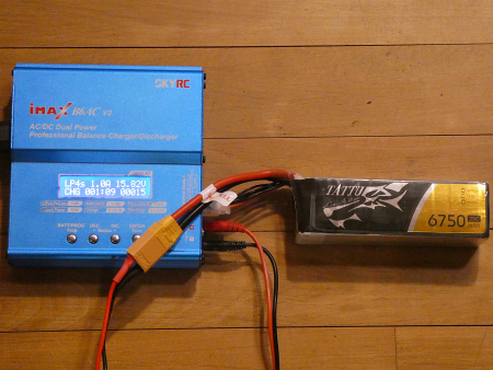
We use an Imax B6AC battery charger with balancer to charge the battery.
Voltmeter and low voltage alarm
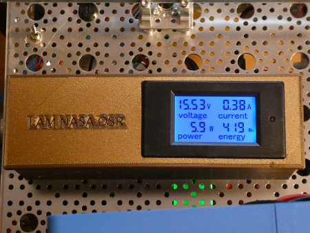
The voltmeter is an DC Volt- Am- and Energy-meter Model PZEM-0,31 (DC 6.5-99 V 0-20 A). An over- and under-volt threshold can be programmed. For us it is important, that the LiPo battery does not go under 3V per cell, so we set the under-volt threshold to 13 V.
The display does blink put there is no sound to warn of undervoltage. So we add a low voltage buzzer alarm to the balancer connector of the battery!
Power circuit
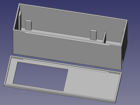
Housing for Battery and Voltmeter
A housing was designed with FreeCAD using a macro (https://www.weigu.lu/other_projects/freecad/freecad_3dbox_macro/index.html). It is fixed at the top of the rover (picture below). The lid clips on the case, so it is easy to change the battery. The files are on github.
Control board PCB
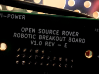
We use the version V1.0 rev_E. Download the zip file from https://github.com/nasa-jpl/open-source-rover/releases/tag/v3.0.0 and unzip it to get the schematic, assembly instructions etc..
Schematic
Power and data signal distribution for the rover is done by the Control board PCB (our first version required you to run each of these wires by hand). The board takes in battery power and distributes it to to each of the voltage regulators and motor controllers. It also takes in encoders from the motors and distributes them to the motor controllers. It also provides serial UART communication between the RPi and the Motor controllers.
Motors and RoboClaws
We have 5 RoboClaw 2x7A Dual Channel Brushed DC Motor Controller to control the 10 gear-motors.
All the motors are from Pololu (25D metal gearmotors). The are brushed, need 12 V and are low power (LP). All the motors have a gear ratio of 172:1 that gives us 5600/172 = 33 rpm. The 6 Pololu drive motors need 12V.
Connections drive motors to the RoboClaw:
| Motor pin nr | wire color | RoboClaw pin |
|---|---|---|
| 1 | red | motor power + |
| 2 | black | motor power - |
| 3 | green | encoder power GND |
| 4 | blue | encoder power +5V |
| 5 | yellow | encoder out A |
| 6 | white | encoder out B |
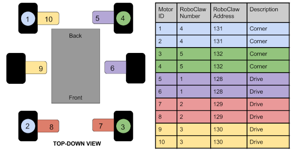
Numbering of the motors with addresses::
Serial communication with RoboClaws
All RoboClaw controller are connected directly to the RxD/TxD serial pins of the Raspi. RxD is pulled high to 5V!
Serial connection RoboClaw to Raspberry Pi:
| Raspberry pin nr | wire color | RoboClaw pin | direction |
|---|---|---|---|
| 8, GPIO14, TxD | green | S1 RxD | |
| 10, GPIO15, RxD | yellow | S2 TxD |
The serial communication works like a bus. It is called Packet Serial. Each RoboClaw has his own address (128-132).
    drive_rc_addr = {'RC_DF':128,  # addresses for roboclaw drive motors RC_DFront
                     'RC_DM':129,  # RC_DMiddle
                     'RC_DB':130}  # RC_DBack

    corner_rc_addr = {'BR':131, # addresses for roboclaw corner motors
                      'FR':131, # RIGHT side M1 = front right, M2 = back right
                      'FL':132, # LEFT side  M1 = front left, M2 = back left
                      'BL':132}
Packet Serial
In packet serial mode RoboClaw can control direction and speed of each motor. Each RoboClaw is assigned a unique address. There are 8 addresses available. This means up to 8 RoboClaws can be on the same serial port. Encoders are supported in Packet Serial mode. All the information are in the RoboClaw user manual page 58.
Serial communication
Enabling serial0 (ttyS0, header)
Raspi 4 with Pi OS (64 bit, release 2025-10-01)
The NASA robot communicates through the native serial port (ttyS0) with the Raspberry Pi 4. When Bluetooth was added to the newer Raspis, the hardware serial port (ttyAMA0) was taken away from the GPIO header and replaced by a “miniUART” (partly software and a bit flaky).
| device | connected to | UART | maps to |
|---|---|---|---|
/dev/ttyAMA0 |
Bluetooth | PL011 hardware UART (UART0) | /dev/serial1 |
/dev/ttyS0 |
GPIO serial port BCM14 and BCM15 | miniUART (UART1) | /dev/serial0 |
First we enable the UART. We can do this in the GUI, or with the command sudo raspi-config in the shell (3 Interface Options, I6 Serial Port). Let's do it in the shell.
The question "Would you like a login shell to be accessible over serial?" is answered with No, and the second question "Would you like the serial port hardware to be enabled?" is answered with Yes.
The first action removes the text console=serial0,115200 from the text line in /boot/firmware/cmdline.txt, and the second action adds the line enable_uart=1 to the file /boot/firmware/config.txt.
We disable serial-getty@ttyS0.service because it has some level of control over serial devices and it can create weird errors:
    sudo systemctl stop serial-getty@ttyS0.service
    sudo systemctl disable serial-getty@ttyS0.service
    sudo systemctl mask serial-getty@ttyS0.service
Then we add the user to the tty group and reboot:
    sudo adduser $USER tty
    sudo reboot
Test if everything is ok with:
ls -l /dev/serial*
We should now see something like this:
lrwxrwxrwx 1 root root 5 Oct 4 07:11 /dev/serial0 -> ttyS0
Switching to hardware serial
We would like to use hardware serial for the motors and miniUART for Bluetooth. This can be done by adding a line to the config file:
sudo nano /boot/firmware/config.txt
Add to the end:
dtoverlay=miniuart-bt
Save (Ctrl+s) and exit the file (Ctrl+x).
    sudo reboot
    ls -l /dev/serial*
The output now shows that the hardware serial is connected to serial0!
lrwxrwxrwx 1 root root 7 Oct 4 07:29 /dev/serial0 -> ttyAMA0
Testing serial0
If the Raspi is not already in the rover we can do this by connecting the header pins with a computer (USB-Serial adapter, 3V!, don't connect the red wire, cross RxD, TxD)
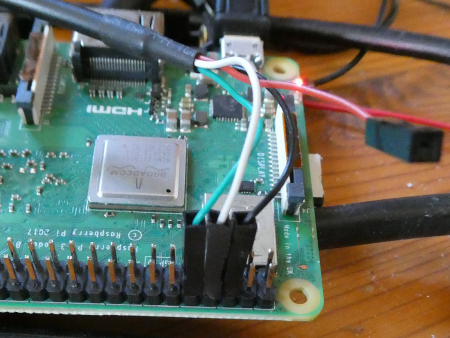
Than we can use minicom on the Raspi (and PC) to test the serial connection with the miniUART.
    sudo apt install minicom
    minicom -b 115200 -D /dev/serial0
If the Raspi is already connected with the roboclaws we can use this python test program: https://github.com/nasa-jpl/osr-rover-code/blob/v2-humble/scripts/roboclawtest.py.
Run the script with:
python roboclawtest.py 128
The result should be something like this:
Connected to /dev/serial0.
(1, 'USB Roboclaw 2x7a v4.2.8\n')
(1, 0, 128)
Bluetooth communication
We use an USB bluetooth adapter with a short cable so that it does not reside in the Faraday cage (beneath ethernet socket at the front, picture above)).
Install some packages
First we install some bluetooth packages:
sudo apt update && sudo apt install bluetooth xboxdrv evtest jstest-gtk
Start bluetooth in the GUI or in the terminal (unblock it with rfkill if bluetooth is blocked):
    sudo systemctl start bluetooth
    sudo rfkill unblock bluetooth
    rfkill list bluetooth
Pairing the Xbox Controller
We turn the Xbox Controller on by pressing and holding the Xbox button X until it lights up.
Then we enter Pairing Mode by pressing and holding the pairing button ))) on the back of the controller until the Xbox button starts flashing rapidly.
Connect the controller on the GUI
- Open the Bluetooth settings from the system menu.
- Click on “Add Device” or “+” to start scanning for new devices.
- Select your Xbox controller from the list of available devices and follow the prompts to pair it.
Connect the controller on the terminal
This is more complicated. A good documentation is here: https://www.baeldung.com/linux/bluetooth-via-terminal
we use the bluetoothctl command and get an interactive shell to run the bluetooth commands.
showshows us the controller (e.g. E4:5F:01:00:AD:21). If not powered on:power onthe controller, if not discoverable:discoverable onlistif more than one controllerselect E4:5F:01:00:AD:21if more controllerscan onto find the Xbox controller (e.g. 98:7A:14:29:AA:94)devicesto show the devicespair 98:7A:14:29:AA:94to pair the controllerconnect 98:7A:14:29:AA:94to to connect to the controller
To get your event codes from the controller do:
sudo evtest
To calibrate controller:
jstest-gtk
The main software (Python)
The main python script is called lam_nasa_osr.py and it is started with a cronjob at startup.
For this we added the following line to the file /etc/crontab:
@reboot root python3 -u /home/lamnasaosr/LAM_NASA_OSR/Python/lam_nasa_osr.py >> /home/lamnasaosr/LAM_NASA_OSR/lam_nasa_osr_log.txt 2>&1
The output is send to a log file to find errors if needed.
The file lam_nasa_osr.py relies on the following modules:
roboclaw_3.py:
The roboclaw module from basicmicro. We named it roboclaw_3 because there is still a version in the net using Python 2.7 instead of Python 3.lam_nasa_osr_config.py:
Contains some config data like RoboClaw addresses and max values for the corner motors.lam_nasa_osr_serial.py:
It handles the serial communication with the display, especially a simple packet communication with a preamble and a CRC at the end. The communication with the Teensy 3.2 (Arduino) uses an USB-TTL adapter and is namedttyUSB0. The data send is one byte defining the screen (image) to display.lam_nasa_osr_rc_motors_encoders.py:
A module with functions to drive the motors.time:
For the sleep function (included in Python).threading:
The communication with the XBox controller must run in its own thread (included in Python).subprocess:
For the possibility to shutdown the Raspberry Pi from Python (included in Python).evdev:
We need the linux input system for the bluetooth communication with the XBox controller. Install it withsudo apt install python3-evdev.serial:
Needed by the serial module. Install it withsudo apt install python3-serialif not already installed..
There are also some test programs in the subfolder test_scripts, and there is a function to get the xbox controller buttons in the main script.
The Software is on github (https://github.com/weigu1/lamnasaosr)
The display software (Arduino)
The display is driven by a microcontroller called Teensy 3.2 sitting on a breakout board (Teensy 3 shield v.4.0).
The software uses an according library called SmartMatrix. More infos: https://github.com/pixelmatix/SmartMatrix and in the corresponding Wiki.
The software catches serial packets and decode them. The incoming data byte defines the image to show.
The images are 64x32 pixel map png pictures. You can use every image you want. Crop it to 2:1 and scale it to 64x32 pixel and save it as png (e.g. with gimp).
With the free software gimp we can export the file to a C source file and include this file to our Arduino sketch (e.g. #include "eyes_angry.c").
Create 64x32 pixel map picture with gimp
Load a picture, crop it to 2:1 and scale it to 64x32 pixel (Image -> Scale Image...). Export it as backup source png-file to a directory with your pictures (File -> Export As..., file type "png"). Then we export the same file as C source code (File -> Export As..., file type "C source code").
Open the file with an editor and replace the matrix name gimp_image with a name you want to use for your picture (e.g. LAM_logo). Now we can include this file in our Arduino sketch and display the picture.
Downloads
Interesting links
- OSR hardware (unzip the file to get schematic, assembly instructions etc.): https://github.com/nasa-jpl/open-source-rover/releases/tag/v3.0.0
- OSR code: https://github.com/nasa-jpl/osr-rover-code
- RoboClaw data sheet: https://downloads.basicmicro.com/docs/roboclaw_datasheet_2x7A.pdf
- RoboClaw user manual: https://downloads.basicmicro.com/docs/roboclaw_user_manual.pdf
- https://spellfoundry.com/2016/05/29/configuring-gpio-serial-port-raspbian-jessie-including-pi-3-4/
- PZEM-031 data sheet:
- https://www.raspberrypi.com/documentation/computers/configuration.html#configure-uarts
