Microcontroller projects
Kyub hacks (|| )
Short description
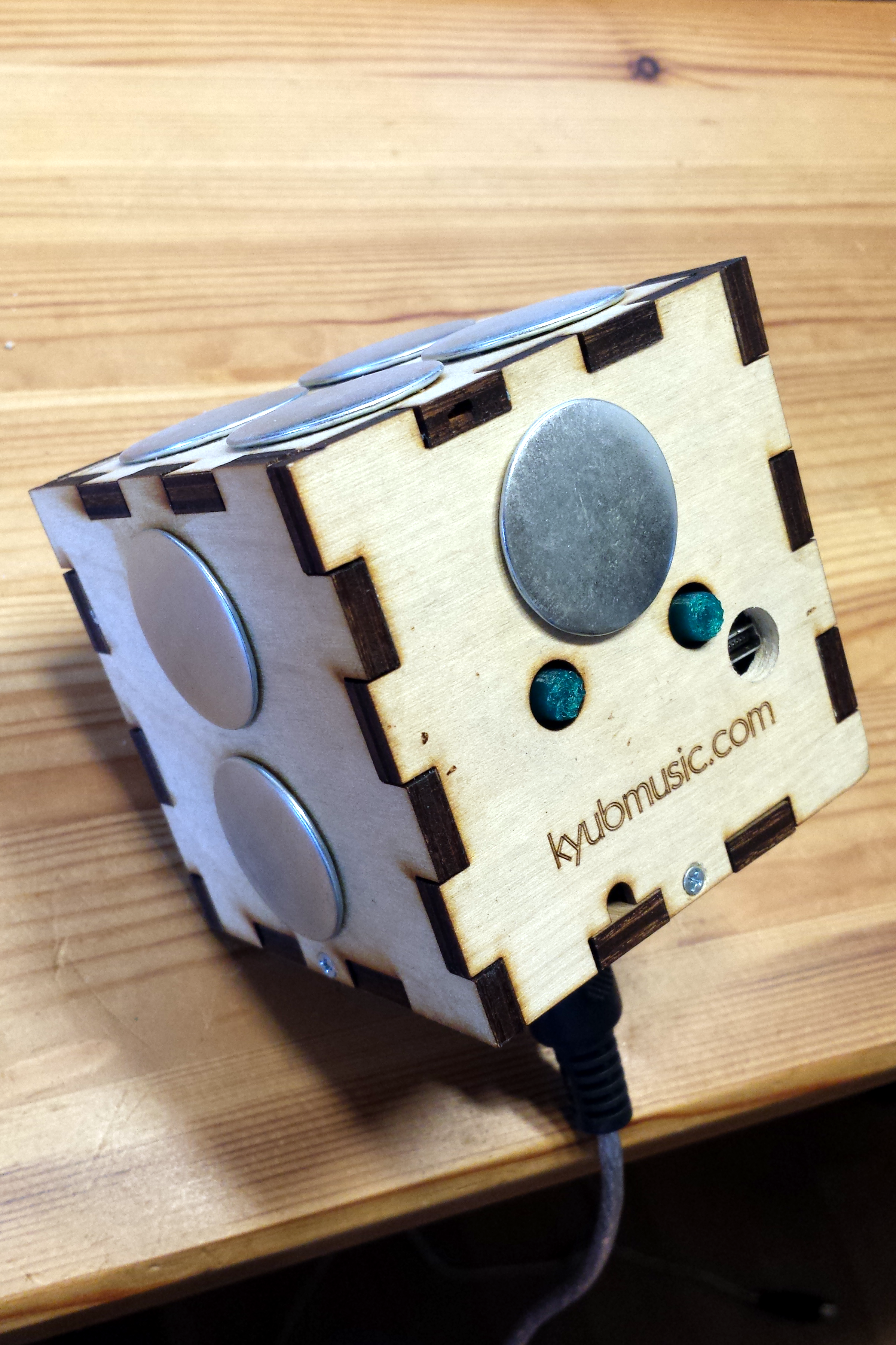
The Kyub is a special MIDI keyboard in the shape of a cube with capacitive sensing and an internal accelerometer based on a Teensy2. Kyubmusic.com does not exist anymore, but some infos are on [hackaday.io](https://hackaday.io/project/701-kyub-midi-controller)
The hacked Kyub
First and second hack:
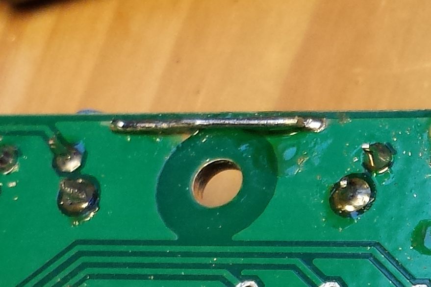
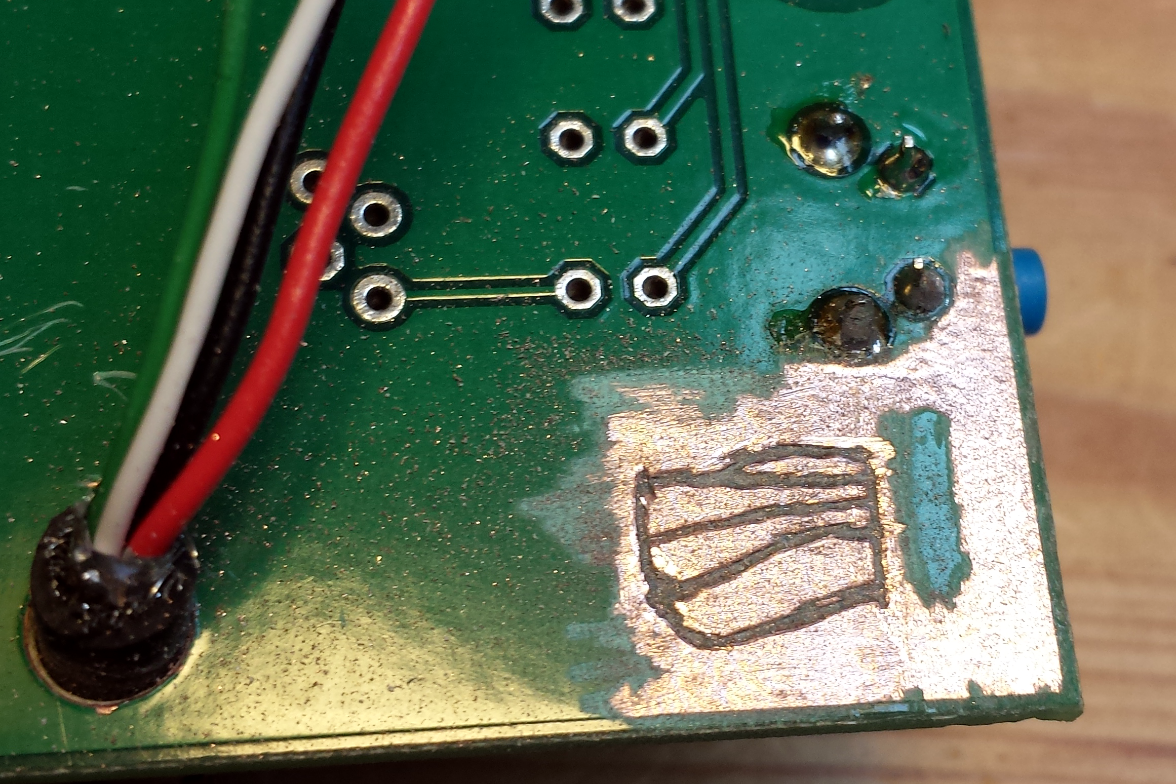
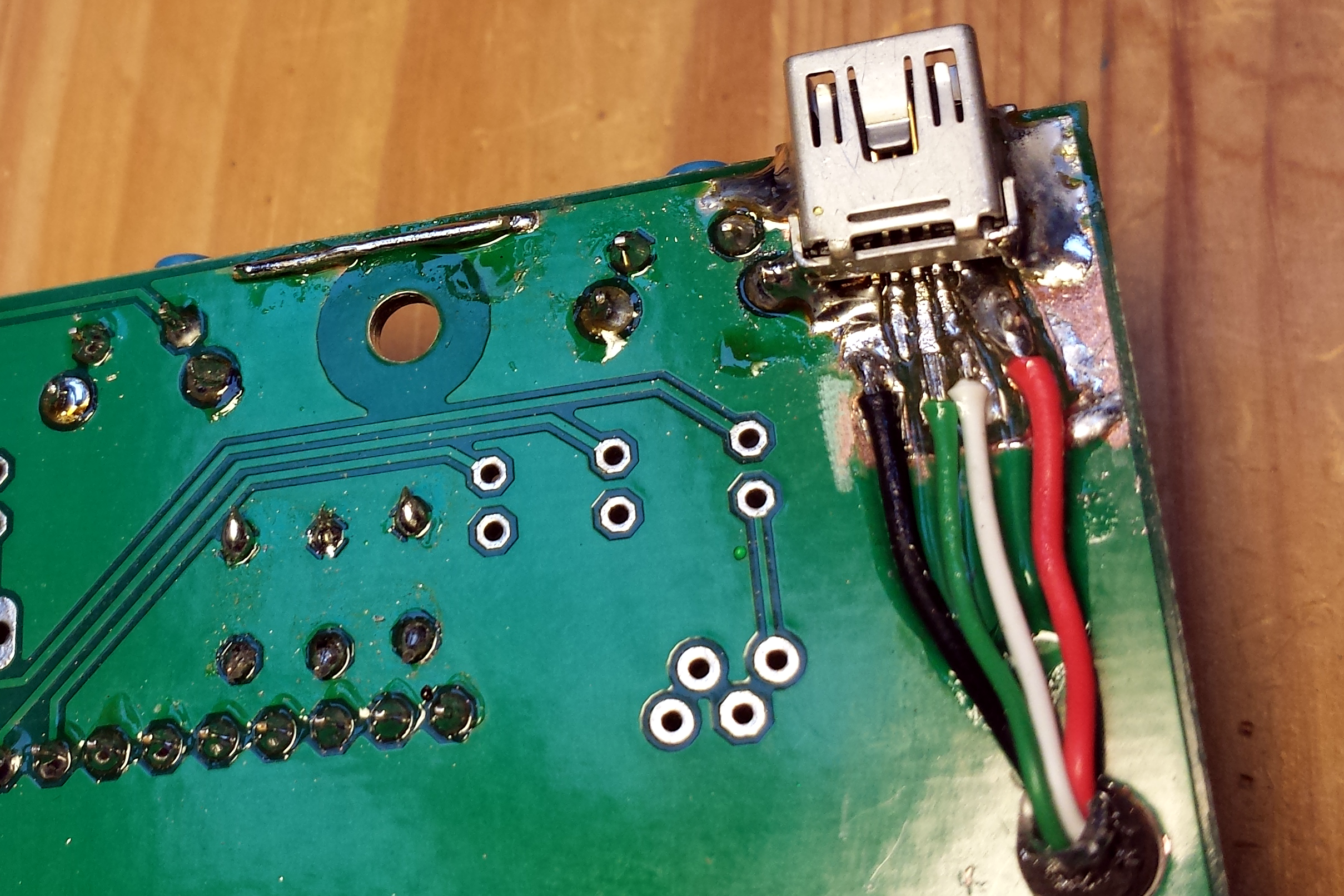
The first hack is in fact the repair of a bug. The Kyub-PCB has a missing connection between two ground plains. The reset button gets no ground and a reset is not possible. A wire connects now the two plains. I want to use the Kyub with a MIDI-cable to connect it to real synths and only alternatively over USB to a PC. For the second hack a USB-connector is soldered to the PCB to get rid of the fixed USB-cable With a handful of components, no need to draw a layout. The circuits are mounted on breadboards: [](png/midi_xbee2.png) [](png/midi_xbee2_back.png) .
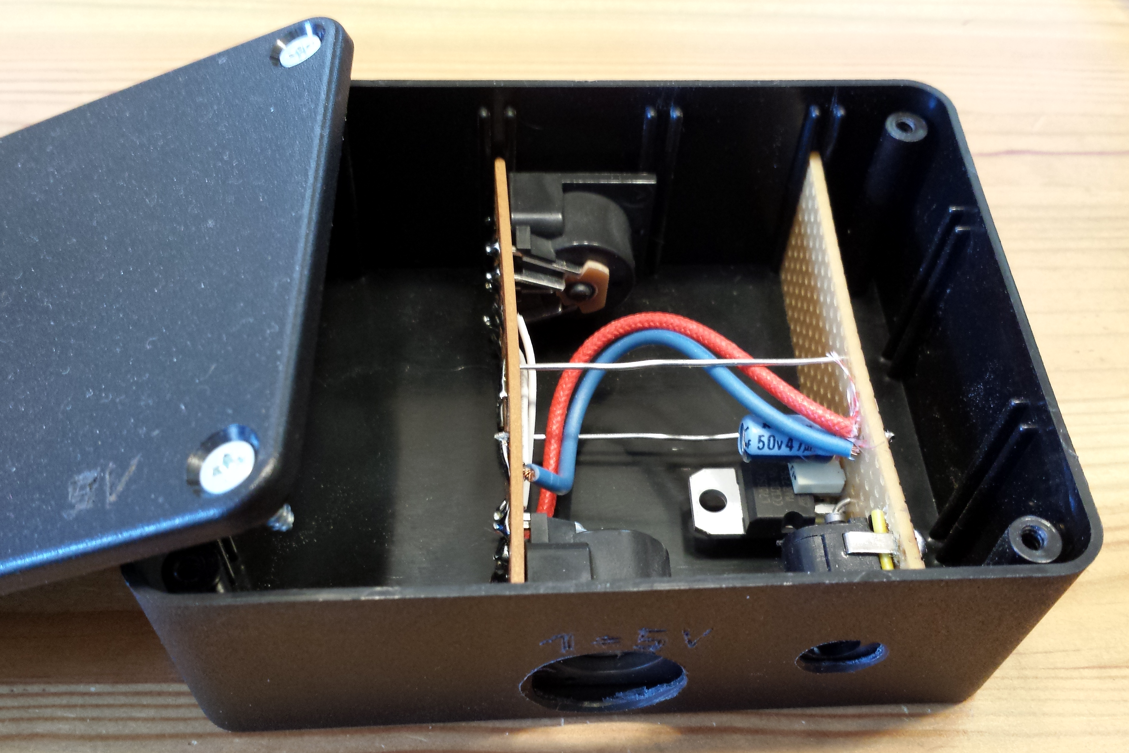
Third hack fourth hack:
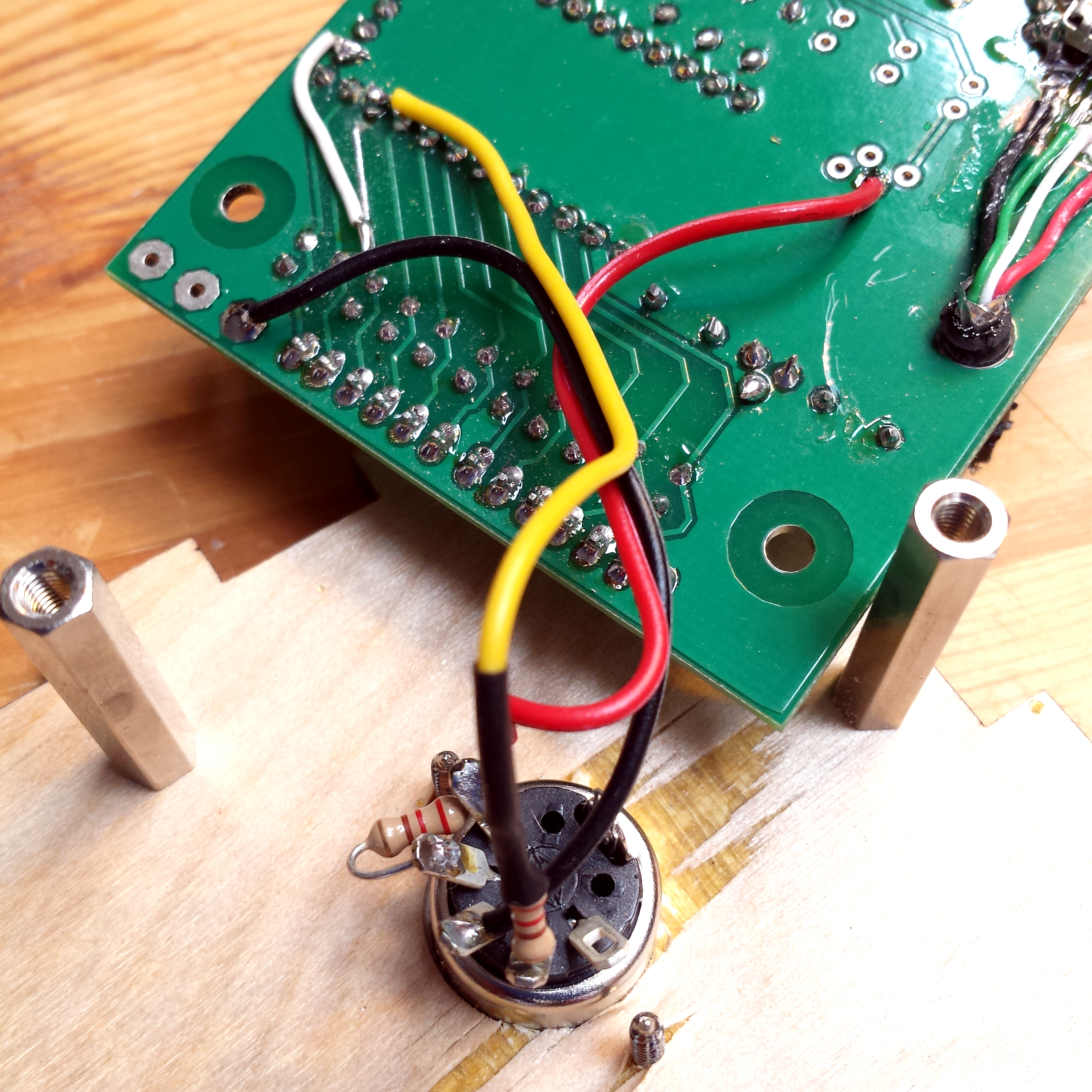
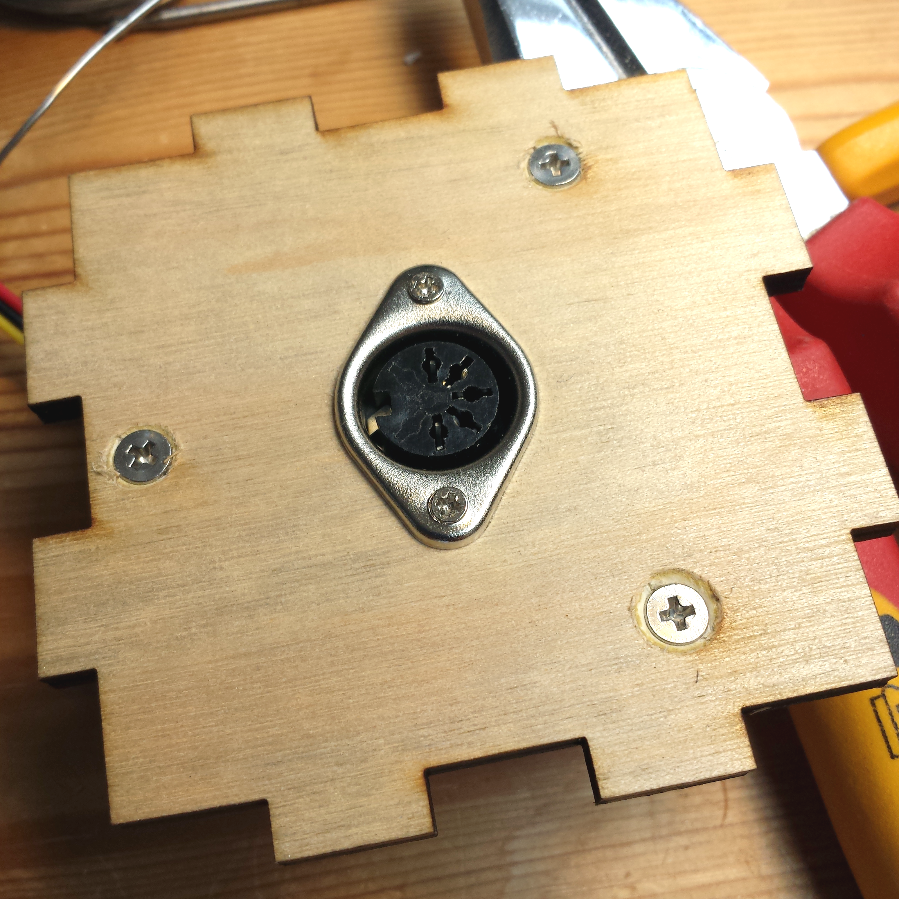
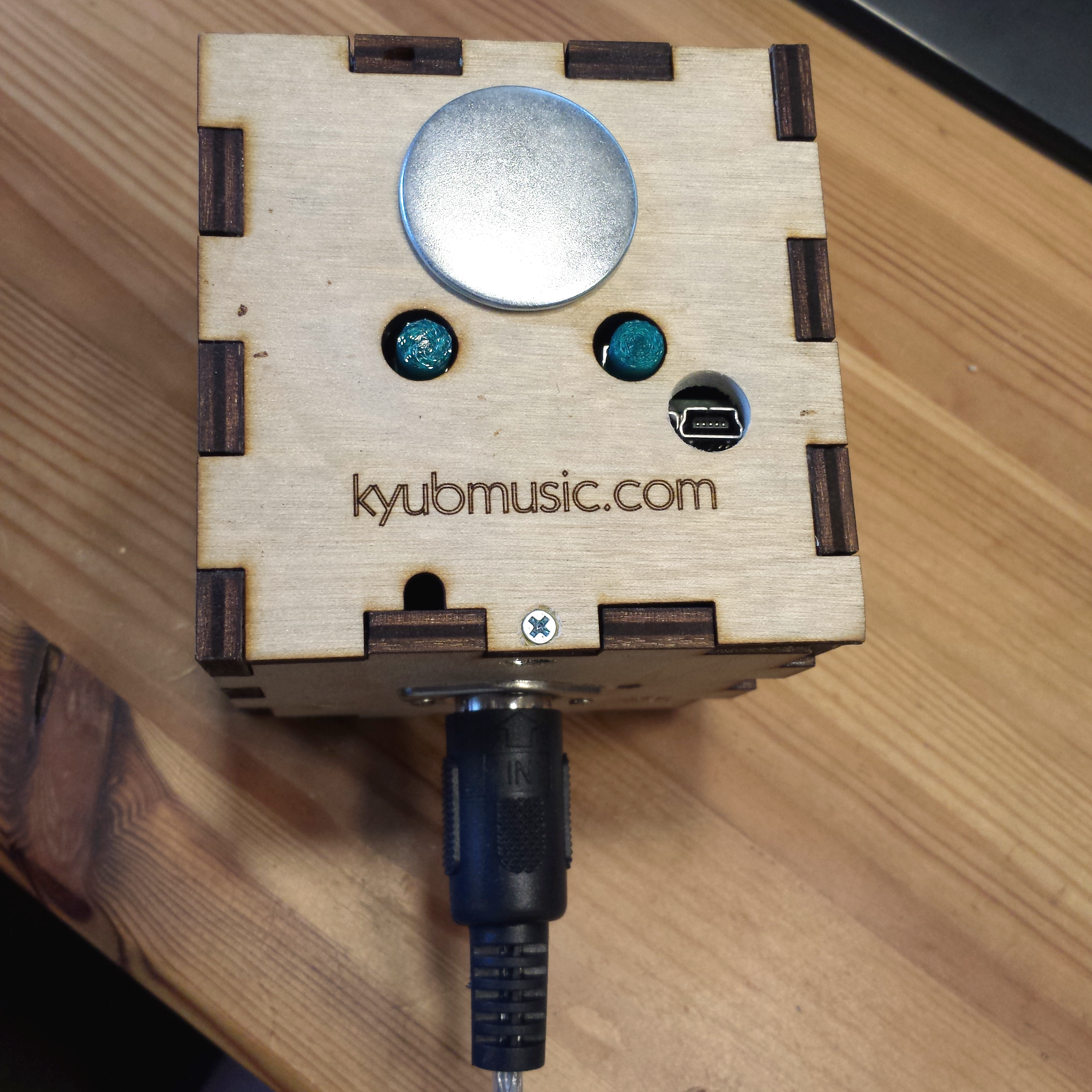
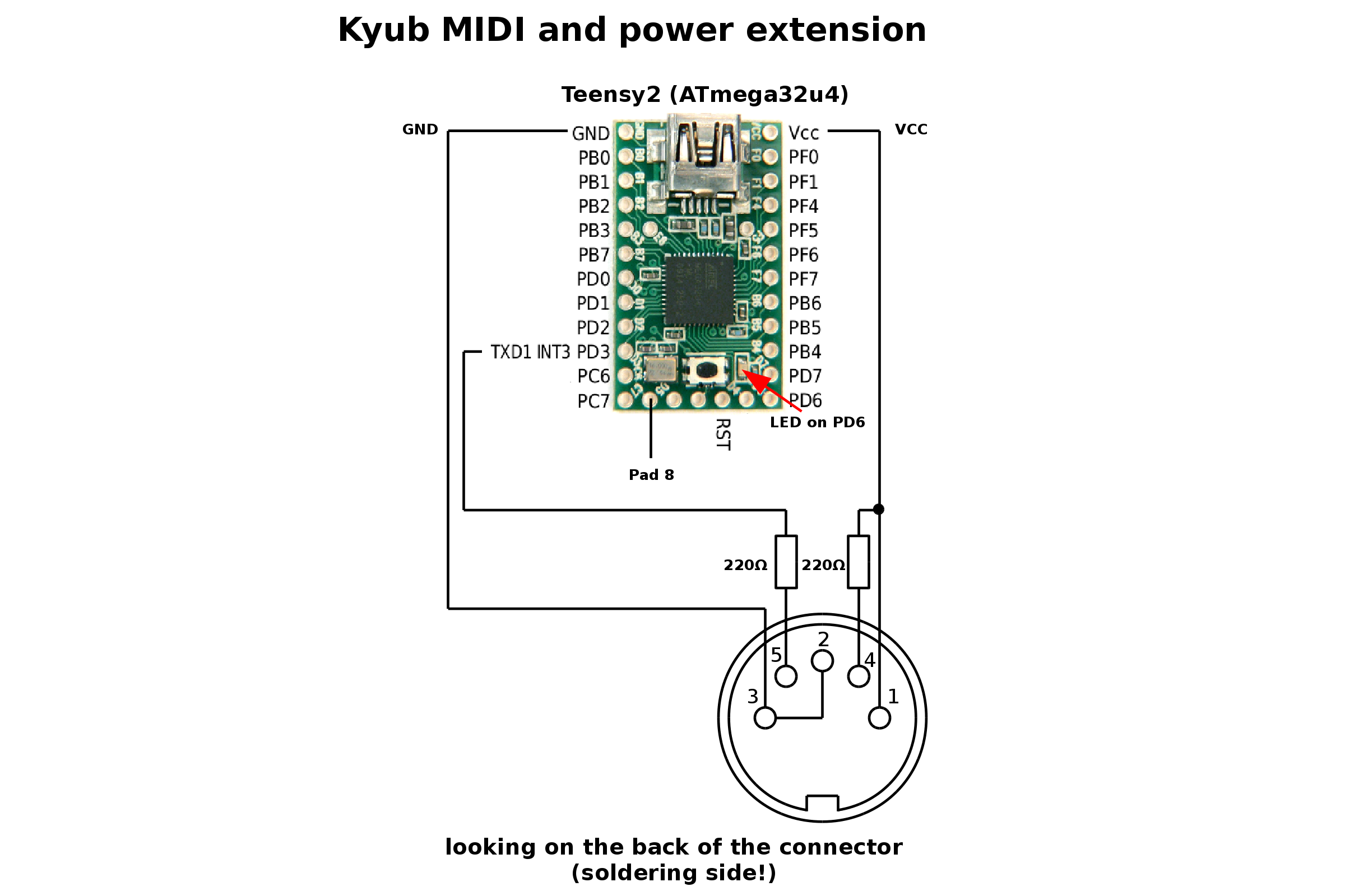
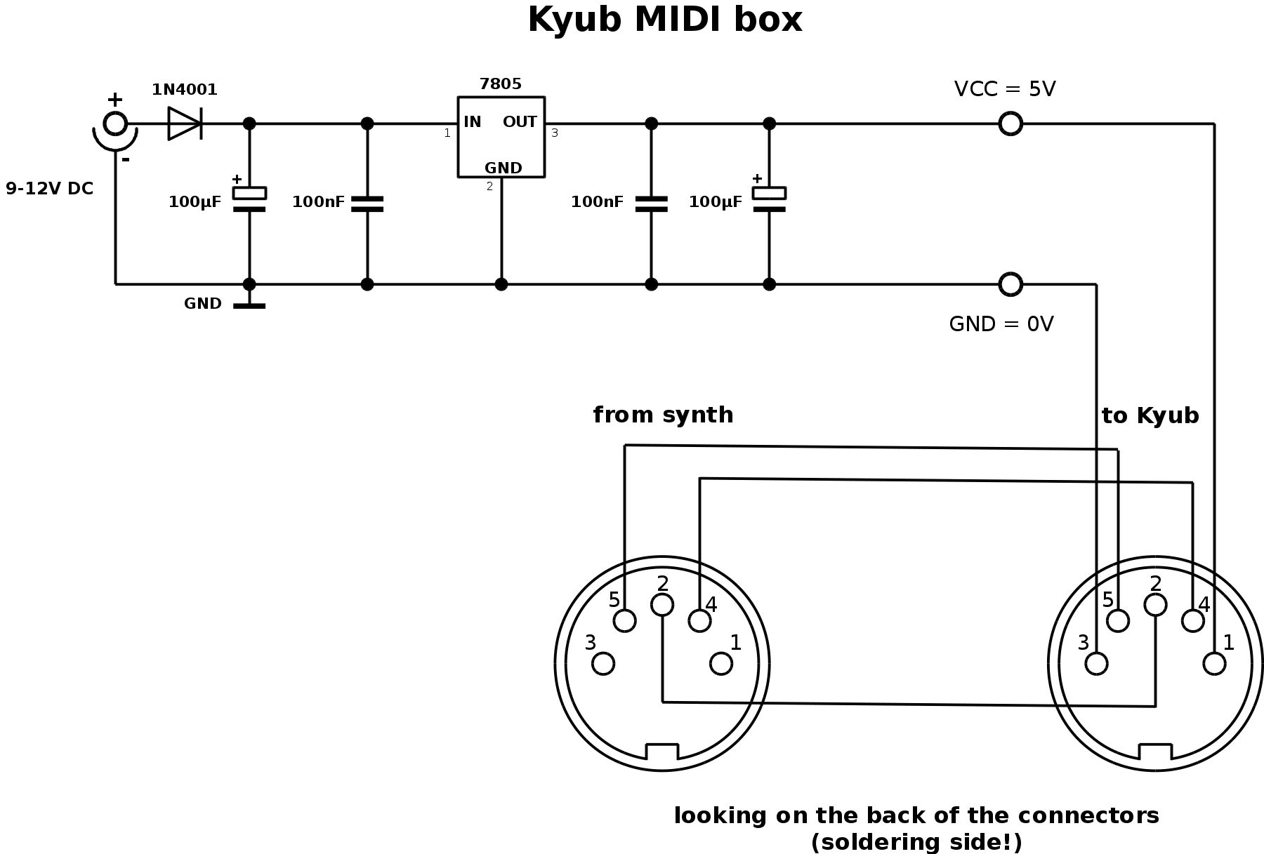
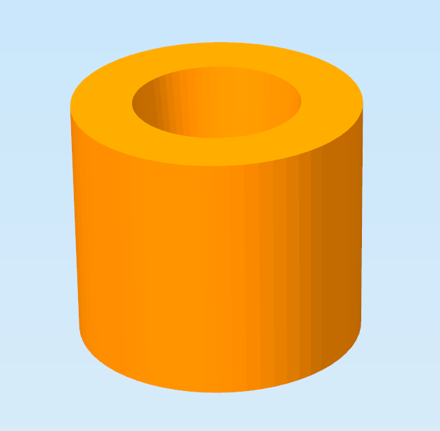
Now a MIDI-connector is needed to send MIDI-data. I use the internal UART of the Teensy on PD3 (TXD1, Arduino pin 8). The pad from this pin is removed to PD5 (Arduino 23). The two free MIDI pins (1, 3) are used to power the Kyub (on the photo the bridge from 3 to 2 is missing). !Carefull! If you do this you have to be sure this pins are not used otherwise by your synth. A little break-out box helps getting power if it is not possible to get it from the synth. The push-buttons of the Kyub are not reachable without help. Two caps from the 3d-printer are helping here.
Software hacks
After analysing the arduino software, I wanted to test the kyub with assembler (yes I like assembler).
The capacitive sensing
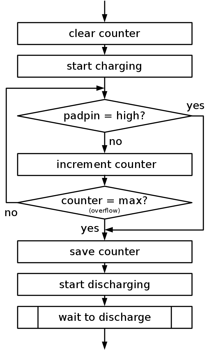
The pad (a capacitor to ground) is charged and discharged over an 1MΩ resistor by the driverpin. When the pad is touched, the capacity gets bigger and the time to charge and discharge is longer. To detect the touch, it is sufficient to lock at the charge time! A calibration is not necessary because the charge time, if not touched, is very steady. Here is the code and a flowchart:
        clr     Tmp1
        sbi     DPPORT,DPNR     ;driverpin high start charging
LOOP1:  sbic    P0PIN,P0NR      ;(2T) 6T=6/16us = 0,375us*256: overflow at 95us
        rjmp    GO1
        inc     Tmp1            ;(1T)
        cpi     Tmp1,255        ;(1T)
        brne    LOOP1           ;(2T)
GO1:    sts     CTIME+0,Tmp1    ;save charge time
        cbi     DPPORT,DPNR     ;driverpin low start discharging
        rcall   W100us          ;Wait to discharge
To see if the pad is touched, the counter value is compared to the threshold (about 20 in my code). To define, if a MIDI note has to be send the old counter value is also saved. So MIDI NotOn (0x90 (channel 0) + Note + velocity) or MIDI NoteOff (0x80 + Note + 0) are only send if there is a change.
The velocity sensing (accelerometer)
The three ADC-values from the accelerometer (x, y, z) are acquired in the main loop and stored as a base for the later min/max comparison. If a pad is touched, 200 accelerometer values in the pad direction are acquired an the minimum and maximum are defined. The difference*4 defines the velocity of the note (value between 2 and 127).
Debugging
The little USB-HID-library is used for debugging. In EP1_CNT you define the number of bytes to send to the PC (max. 63). The Bytes are written in the SRAM-Buffer (EP1_BUF). If EP1_FLAG is set to 1 the data is valid for the host.
        ldi     Tmp1,2          ;send two bytes
        sts     EP1_CNT,Tmp1
        ldi     Tmp1,100        ;fill buffer with two values
        sts     EP1_BUF+0,Tmp1
        ldi     Tmp1,150
        sts     EP1_BUF+1,Tmp1
        ldi     Tmp1,1          ;set EP1 Flag data available
        sts     EP1_FLAG,Tmp1
On the PC a little Python program gets the data (call with python debug.py):
import hid
import time

h = hid.device()
h.open(0x03eb,0x0002)        #weigu.lu/microcontroller/avr_usb_libs/  VID=0x3EB, PID = 2
byteNr = 2

while(1):
    d = h.read(byteNr)
    pad =[]
    if d:
        for i in range(byteNr):
            pad.append(d[i])
        print pad
h.close()
Downloads
