3D printing
last updated: 2022-02-08
Pimping up the Felix 4.1 with 32 bit, higher voltage and better stepper driver
Quick links
- Introduction
- Collecting data on Felix TEC 4.1
- Duet 3
- config.g
- Homing
- Manual Bed Levelling Assistant (MBLA)
- Using a Mesh Bed Compensation (MBC)
- Pi shutdown
- Downloads
- Interesting links
Introduction
I had problems accepting the long heating up times and the poor possibilities for manual interaction with the new Felix 4.1 firmware. So I tried to change this with a new Duet 3 6HC motherboard. Okay, the true story is that I clicked a little too fast (don't tell my wife) and ordered the beautiful, but quite expensive and perhaps over-dimensioned new motherboard (only later I found the BIGTREETECH-SKR board, with support for Felixprinters. A config example can be found in https://github.com/MarlinFirmware/Configurations/archive/release-2.0.6.1.zip.
What could be the benefits of a new motherboard?
- 19 V instead of 12 V; more power for heating; more torque in the motors
- 32 bit instead of 8 bit, faster calculations
- Better stepper driver (less noise)
- Better supported and more up-to-date firmware
- direct network access, no octoprint needed
- and surly some more
So should I update my Felix? Surely not. It is running quite smoothly and the print results are ok. Never change a running system!
Will I pimp the Felix? Sure enough, because I like to learn and understand new things.
So the first step is to print a test piece to be able to compare print results. I choose the MINI All In One 3D printer test by majda107. The second step is to collect all the data about my printer and the third step is to configure the firmware.
Collecting data on Felix TEC 4.1
Power supply
The power supply is an ENP-7025D from Enhance Electronics and marks 12 V/18 A, 5 V/2 A and 250 W.
Endstops X and Y (optical sensors)
The X and Y end-stops on the Felix are transmissive optical sensors TCST2103 from VISHAY. Cathode and emitter are connected and go to GND.
The Felix build volume in single mode is 205x255x225 mm (L, W, H) and 205x240x225 mm (L, W, H) in dual mode.
Z-probe
Felix 4 uses a shielded proximity sensor from OMRON (Model: E2B-M12KS04-WP-C2 2M). The sensor has an M12 standard thread with a sensing distance of 4 mm. C2 indicates an open collector NPN-Transistor (output) normally closed. The response frequency is 1000 Hz and the power supply voltage may range from 10 to 30 V (10 mA max.).
Stepper motors
The stepper are standard 40 mm NEMA 17 stepper with 1.8° and 1.7 A. In my Felix they are from Wantai (42BYGHW609P1-2).
The stepper use microstepping with 16 steps. So we have 360°/1.8°*16 = 3200 steps per revolution.
The pulley on X and Y has 14 tooth. The toothbelt is a HTD 3M 6GT2 6 mm (width) with 3 mm between the teeth. We get 14*3 = 42 mm per revolution and:
For X and Y we have 3200/42 = 76.1904762 steps/mm.
The Z axes has a 10 mm x 2 mm 330 mm spindle with 2 mm/revolution .
This gives us for Z 3200/2 = 1600 steps/mm.
For both extruders we find a value of 164 steps/mm in the firmware. The circumference of the drive wheel is about 7.5*3.1415 = 23.56 mm. We should get 136 steps/mm? So here I don't know how to the value is calculated.
Heating bed (foil heater) and thermistor (NTC)
No infos from Felixprinters. With my Ohmmeter I measure a resistance of 1.2 Ω. So with 12 V we could expect 10 A. The sensor is a 100k NTC (configuration.h). I measure 95 kΩ.
I will heat the bed first to 60 °C and then to 90 °C and measure current and voltage with my mooshimeter:
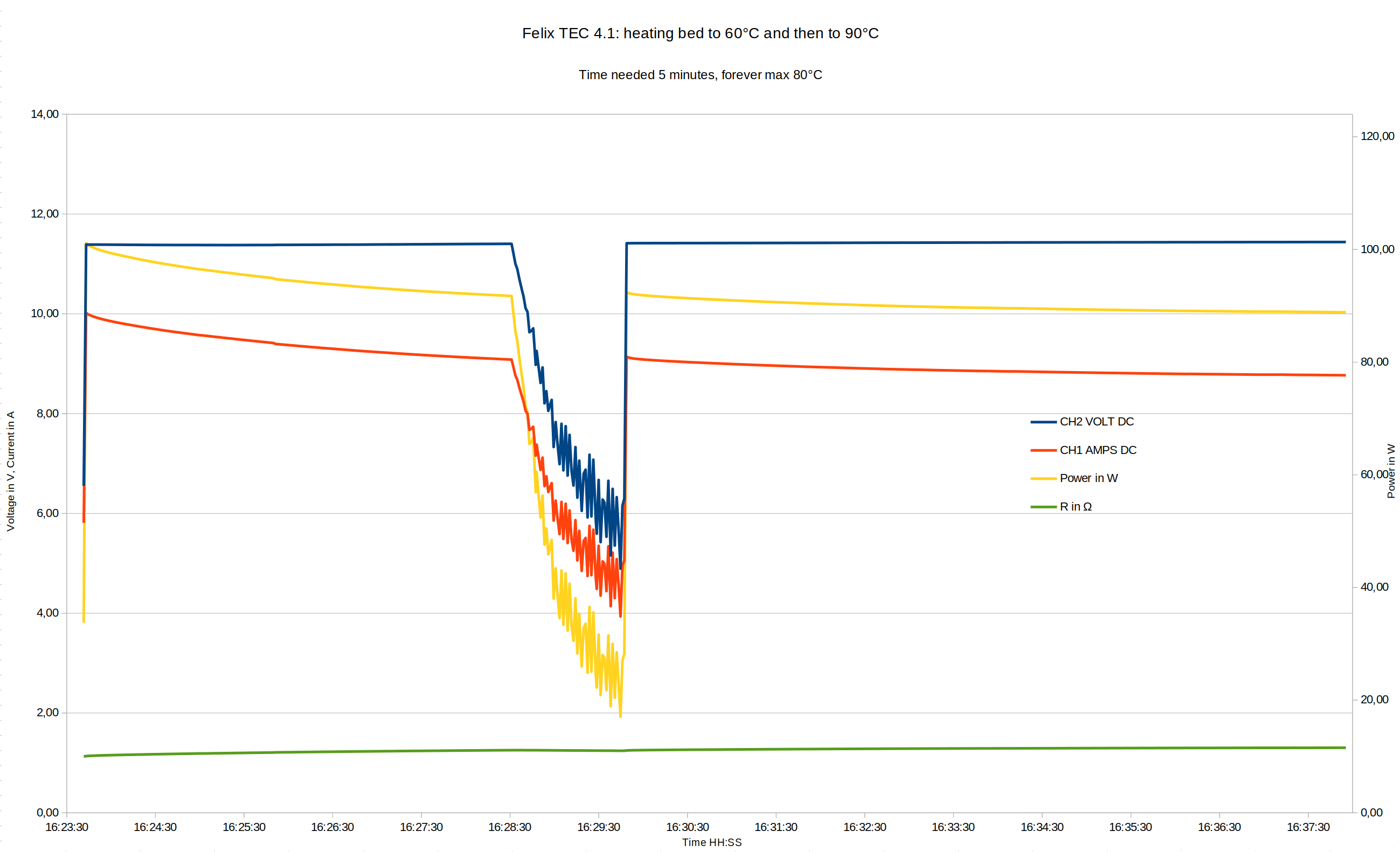
Conclusion: The bed does not reach 90 °C, but a max. of 80 °C! even in a well heated room. So we need more power :). The resistance varies from 1.13 Ω (cold) to 1.3 Ω.
To get to 60 °C we need more than 5 minutes.
Extruder heater cartridge and thermistor (NTC)
Here we get some information from the Felix shop: Heater cartridge: Power 30 W, Voltage 12 V, Resistance 4.7 Ω, Diameter 5.5 mm, Length 10 mm
For the thermistor: It has the same specs as an epcos B57560G104F. It is an NTC (Negative Temperature Coefficient) and we find a good description in the reprap wiki.
With my Ohmmeter I measure a resistance of 4.9 Ω for the heater cartridge. So with 12 V we could expect 2.5 A. For the thermistor I measure 97k Ω.
I will heat the extruder to 210°C and measure current and voltage with my mooshimeter:
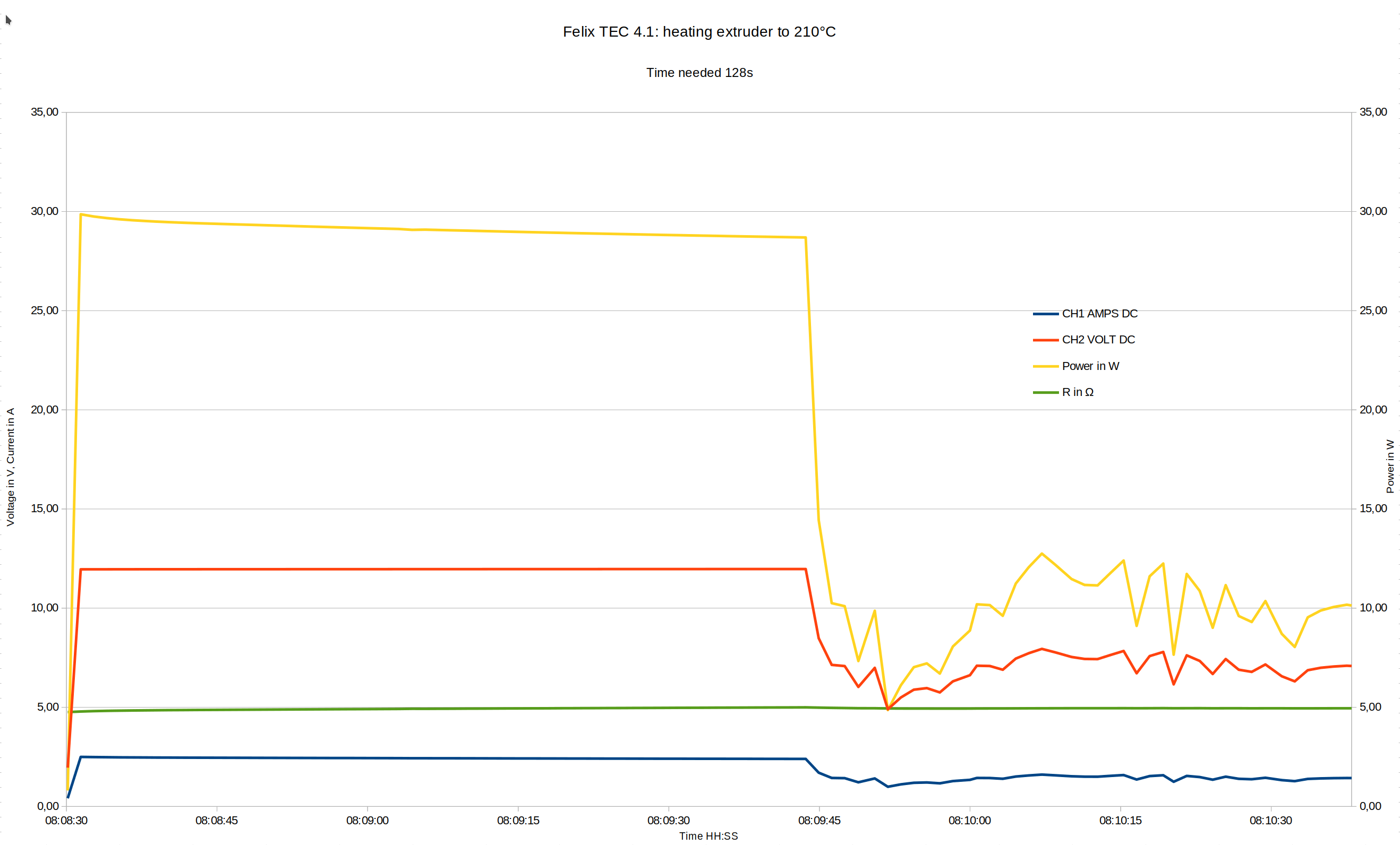
Conclusion: We need 75 seconds. The last 10°C (from 200°C to 201°C) take quite long.)
X and Y optical sensors
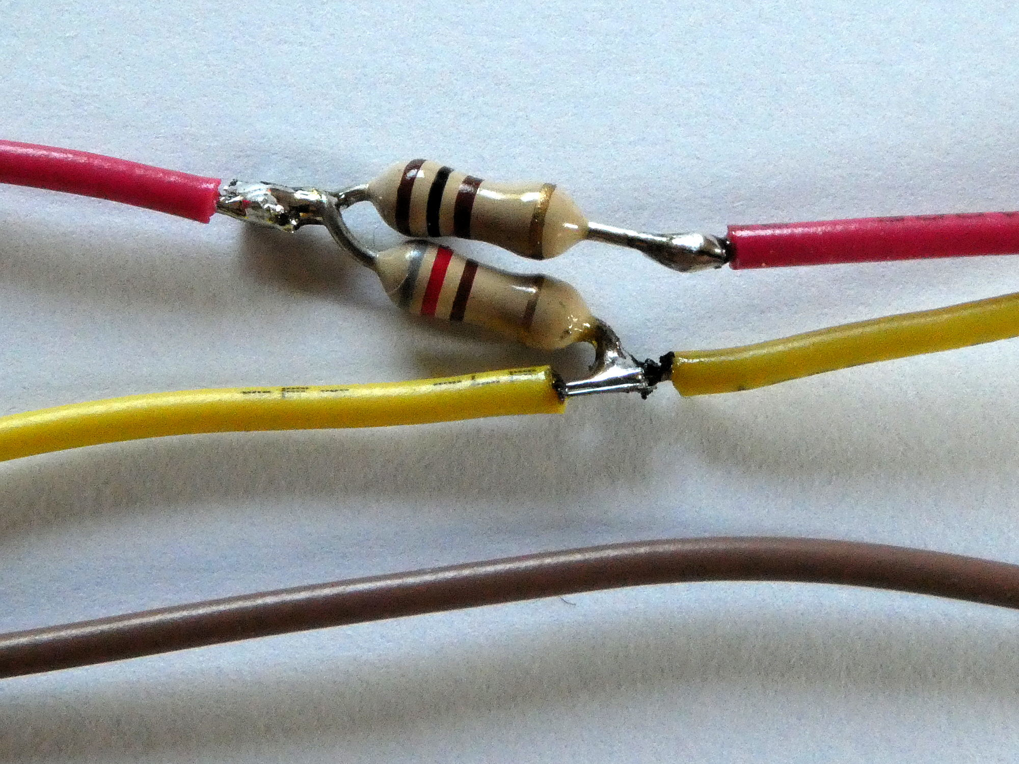
The X and Y end-stops on the Felix are transmissive optical sensors TCST2103 from VISHAY. Cathode and emitter are connected ans go to GND. The LED needs 20 mA. With 3.3V we get a series resistor of about 100 Ω. The current through the transistor should be 4 mA (data sheet), but the internal pull-up is with 27 kΩ too high. We need an 820 Ω resistor in parallel.
Both resistors are soldered into my extension cable.

Z-probe
Felix 4 uses a shielded proximity sensor from OMRON (Model: E2B-M12KS04-WP-C2 2M). The sensor has an M12 standard thread with a sensing distance of 4 mm. C2 indicates an open collector NPN-Transistor (output) normally closed. The response frequency is 1000 Hz and the power supply voltage may range from 10 to 30 V (10 mA max.).
We get 3 wires in a 2 m cable and the colours are a little creepy. Brown for the positive voltage, blue for GND and black for the signal. As we need 12 V we use the extra 2 pin 12 V header of the Duet. No extra resistors are needed as the duet3 inputs will tolerate up to 30V and have an internal pull-up of 27k. (if you have another board, you could use a voltage divider to limit the voltage).

Fans
The fans are Sunon KDE1204PFV211MSA with the following data: 12 V, 80 mA (1 W), 11,89 m³/h, RPM 5800, 27 dBA.
Duet 3
Getting started
Most infos can be found here: https://docs.duet3d.com/User_manual/Overview/Getting_started_Duet_3_MB6HC.
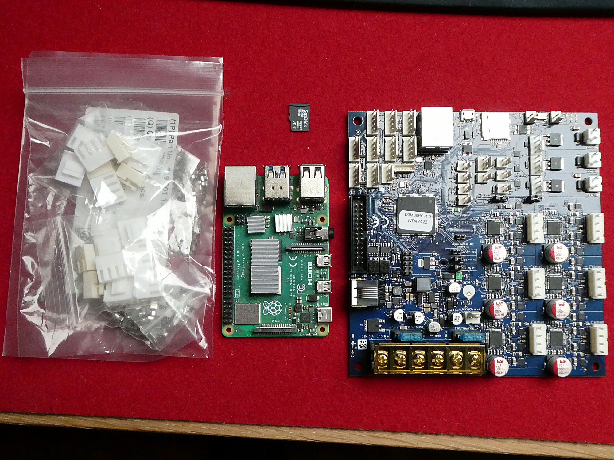
I use the Duet 3 main board with a Raspi 4. The Raspi is connected through a 40-pin ribbon cable to the main board. Through a HDMI screen with touch functions the printer can be operated directly. Through web control this can also be done remotely.
On the Duet3 pages you often find shortcuts. Here some explanations:
SBCis a Single Board Computer e.g. our Raspi 4.DSFis the Duet Software Framework that runs on the Raspberry Pi. It is based on the RaspiOS (debian).The Raspi controls the Duet 3 over SPI. The image for the Raspi is calledDuetPi. The hostname isduet3. As mDNS is enabled (via avahi) you can access the Raspi withduet3.localin your web browser. SSH is activated and uses standard login and password (pi, raspberry). For WiFi, you can editwpa_supplicant.conf.
In the apt sources.list we find the server:https://pkg.duet3d.com stable InRelease.
The framework is installed in:/opt/dsf.
The code is here: https://github.com/Duet3D/DuetSoftwareFramework.DCSis the Duet Control Server. You can start and stop the server withsystemctl(ex.:sudo systemctl start duetcontrolserver).DWSis the Duet Web Server. You can start and stop the server withsystemctl(ex.:sudo systemctl start duetcontrolserver).DWCstands for Duet Web Control. From github: "It is a fully-responsive HTML5-based web interface for RepRapFirmware which utilizes the Bootstrap framework, JQuery and a few other libraries to allow easy control of Duet-based 3D printer electronics. It is designed to communicate with RepRapFirmware using WebSockets and RESTful HTTP requests. One goal of the core application is to keep things compact, so a good loading speed can be achieved even on slow networks. Another one is to communicate to the firmware using only AJAX calls, which either return JSON objects, plain texts or binary blobs".To useDWCtypeduet3.local(or your Raspi IP) in a web browser. If you want to use it on the Raspi itself use127.0.0.1. It can also be used over VNC.
The code is here: https://github.com/Duet3D/DuetWebControl.RRF3stands for RepRapFirmware 3. This 3D printer firmware supports flexible pin allocations so that any output pin can be used to drive a fan, heater or other device. All these allocations have to be made in a file calledconfig.g. More infos in https://docs.duet3d.com/User_manual/RepRapFirmware/RepRapFirmware_overview.
The code is here: https://github.com/Duet3D/RepRapFirmware/releases.
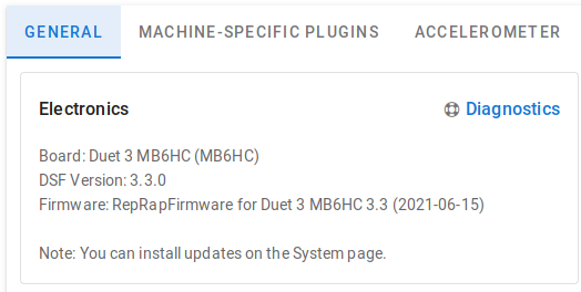
Versions
The actual versions can be seen in DWC under Settings > General (DWC) and Settings > Machine-Specific for RRF and DSF.

Updating the firmware
This is done with a two simple commands over ssh:.
    sudo apt update
    sudo apt upgrade
All latest software components and the latest RepRapFirmware version will be updated.
Another possibility to update the firmware or to use beta versions is to download a firmware .bin file from github and upload the file under Files > System in Duet Web Control.
Changing the hostname
I changed it to hostname with raspi-config to "duet3dual" because I want to use 2 printer with duet. This created the following Error: "M550: Machine name must consist of the same letters and digits as configured by the Linux hostname". So I needed to send:
M550 P"duet3dual"
in DWC.
Power supply
My first 24 V power supply from MeanWell had a fan that was by far too loud. So I bought a passive power supply from (MeanWell HLG-600H-24A, not cheap :().
The power supply delivers 25 A on the 24 V rail. As I want to operate the bed (1.2 Ω) only at 50 % PWM, the mean current should stay under the rated 18 A of the Duet 3 motherboard. But I have the possibility to adjust the voltage down to 19 V. So let's be reasonable and do it with 19 V.
Wiring diagram
Here is the link to the original Wiring Diagram. I used the following connections:

Emergency stop
Safety first. We connect an push-button to the RESET header of the mainboard. This will allow a quicker stop than Clicking in the web control interface. More infos: https://docs.duet3d.com/User_manual/Connecting_hardware/IO_E_stop.
Connecting and configuring the 5 stepper motors
First we connect the 19 V of our power supply to "POWER IN" of the mainboard. As we get two double wires from the power supply I also used the second header (OUT0) connected in parallel.
As stated all configuration will be done in the configuration file config.g, easily accessible through Duet web control under System. The settings are made with G-code commands. Details can be found here.
It is possible to generate this file with the RepRapFirmware Configuration Tool. This is a good start before doing the still needed changes.
This file begins with the General preferences:
    ; Configuration file for Duet 3 (firmware version 3)
    ; executed by the firmware on start-up
    ;
    ; generated by weigu.lu 2020-09-08

    ; General preferences
    G90                                               ; send absolute coordinates...
    M83                                               ; ...but relative extruder moves
    M550 P"duet3dual"                                 ; set printer name (must be Raspi host name!)
Stepper X is connected to Driver 5 (because of the case), Y to Driver 1, Z to Driver 2, left extruder to Driver 3 and the right Extruder to Driver 4. If the direction is not correct, change the two wires of one coil or change the S parameter pf command M569.
With 16 microsteps we get as calculated above 76.19 steps/mm for X and Y and 1600 steps/mm for Z.
Other needed data can be found in the Felix firmware and/or in the Marlin firmware for Felix printers (see links at the bottom of the page).
    ; Drives
    M569 P0.1 S1                                      ; physical drive 0.1 (Y) goes forwards (S1)
    M569 P0.2 S1                                      ; physical drive 0.2 (Z) goes forwards
    M569 P0.3 S0                                      ; physical drive 0.3 (E0) goes backwards (S0)
    M569 P0.4 S0                                      ; physical drive 0.4 (E1) goes backwards
    M569 P0.5 S1                                      ; physical drive 0.4 (X) goes forwards
    M584 X0.5 Y0.1 Z0.2 E0.3:0.4                      ; set drive mapping
    M350 X16 Y16 Z16 E16:16 I1                        ; configure microstepping with interpolation
    M92 X76.19 Y76.19 Z1600.00 E164.00:164.00         ; set steps per mm
    M566 X600.00 Y600.00 Z18.00 E228.00:228.00        ; set maximum instant. speed changes (mm/min)
    M203 X12000.00 Y12000.00 Z600.00 E1800.00:1800.00 ; set maximum speeds (mm/min)
    M201 X1100.00 Y1100.00 Z100.00 E10000.00:10000.00 ; set accelerations (mm/s^2)
    M906 X1275 Y1275 Z1275 E1275:1275 I20             ; set motor currents (mA) and idle factor (%)
    M84 S20                                           ; Set idle timeout
Connecting and configuring the axis limits and the endstops
As the Felix build volume is 205x240x220 mm (L, W, H) in dual mode we set the axis maxima accordingly with the M208 command.
Next we connect the end-stops to IO0 and IO1 for X and Y and to IO6 for Z as shown above.
To test and calibrate the Z probe use the following link: https://docs.duet3d.com/User_manual/Tuning/scanning_z_probe_calibration.
For G31: I found in the docs: "When the probe is to the left of the nozzle the X value is negative. When the probe is in front of nozzle the Y value is negative". Here it is not clear where is left and front at it took me some hours to find out that the values must be positive for the Felix!
My probe is 7 mm left of the right extruder and before the extruder by 35 mm.
So : G31 P500 X7 Y35 Z0.5.
M557 defines the mesh grid for the Mesh Bed Compensation (MBC). Here we have to use the probe values for the starting values, to avoid warnings by the G29 command.
With the M671 command we can also define the screws of our bed, so that later on bed probing is possible with the G32 command (see chapter: Manual Bed Levelling Assistant). But because G32 uses the file bed.g we define M671 in that file.
    ; Axis Limits
    M208 X0:240 Y0:205 Z0:200                         ; set axis minima and maxima

    ; X and Y Endstops
    M574 X1 S1 P"io0.in"                              ; configure active-low endstop (X) pin io0.in
    M574 Y1 S1 P"io1.in"                              ; configure active-low endstop (Y) pin io1.in

    ; Z-Probe
    M558 P5 C"io6.in" H5 F60 T6000                    ; set Z probe type to unmodulated
                                                      ; and the dive height + speeds
    G31 P500 X7 Y35 Z0.5                              ; set Z probe trigger value, offset
                                                      ; and trigger height
    M557 X7:240 Y35:200 S20                           ; define mesh grid (use probe values!)
    ;M671 X110:40:40 Y94:231:-38 P0.5                 ; this is not needed here; look in bed.
#### Connecting and configuring the heated bed
Now things get a little more exciting. We will connect the heated bed to 19 V instead of 12 V. Bridge the 19 V to "OUT 0 POWER IN" and connect the bed to "OUT 0".
The trick is to reduce the PWM to a limit that can not damage the foil heater. The resistor of the bed foil stays the same. If we double the voltage, also the current will double. So power increases in square. So let's begin with a maximum duty cycle of 25 % for the PWM. In the first test tries I still used 24 V instead of 19 V.
<big><center>**Danger!! Don't forget to reduce the PWM duty cycle! All experiments are at your own risk!**</big></center>
We will use PID and no bang bang mode!
Now we get 2 possibilities:
+ First-order + delay time (FOPDT) model: Use auto-tuning (or configure manually using `M307`). We get two sets of PID parameters.
+ Use one set of legacy PID parameters configured manually using M301. This provides a fallback if the behaviour of your heating system cannot be approximated well enough by a FOPDT model.
Autotuning is done with the `M303 H0` for heater 0 command. With `S` we set the temperature and with `P` we can set the PWM duty cycle. After autotune is completed the `M307 H0` command shows the results.
More infos on: <https://docs.duet3d.com/User_manual/Connecting_hardware/Heaters_tuning>
Autotuning Heater bed with 12 V to 60 °C and a duty cycle of 100 % gives us the following data:
Heater 0 model: gain 81.3, time constant 436.2, dead time 6.8, max PWM 1.00, calibration voltage 12.2, mode PID
Computed PID parameters for setpoint change: P141.2, I2.594, D670.7
Computed PID parameters for load change: P141.2, I6.443, D670.7
The peak temperature was 60.5 °C and the tuning took 687 s. Heating up takes about 5 minutes.

Same procedure with `M303 H0 P0.25 S60` and 24 V (target temperature 60 °C, PWM 0.25 %, here I used still 24 V).
Heater 0 model: gain 83.9, time constant 454.7, dead time 6.2, max PWM 0.25, calibration voltage 24.0, mode PID
Computed PID parameters for setpoint change: P155.1, I2.911, D677.5
Computed PID parameters for load change: P155.1, I7.459, D677.5
I get a peak temperature of 60.6°C and the tuning took 722 s. We need 4 minutes and 48 seconds. So double the voltage to 24 V 25 % of the time gets the same result as steady 12 V.
Now let's double the power to get better heating times.
12 V with 1.2 Ω gives 120 W. To get 240 W with 19 V we need a current of 12.6 A. 19 V on 1.2 Ω gives 15,8 A. The PWM could be at 80%. I choose 75 %.
The default PWM frequency was 250 Hz and produced a very loud sound as the bed acts as a loudspeaker. I thought the solution would be to increase the frequency to 15000 Hz with the `Q` parameter of the `M950` command. The heating took a little longer but now there is no sound. Then I smelled hot electronics. With my camera I saw that a transistor heated up to 140 °C!! So clearly the frequency was too high! So I reduced the frequency to 50 Hz!! Here is the answer to this problem from dc42 in the forum: <https://forum.duet3d.com/topic/18592/beware-of-too-high-pwm-frequency-on-out-0>.
Autotuning Heater bed with `M303 H0 P0.75 S60` (target temperature 60 °C, PWM 0.75 %, freq. = 50 Hz).
I get a peak temperature of 61.1 °C and the tuning took 477 s. The parameters considerably changed!
**The heating up to 60 °C takes only about 2 minutes and 20 seconds instead of 5 minutes!**
Here is the output with 50 Hz (`M307 H0`):
Heater 0 model: gain 120.8, time constant 345.8, dead time 5.4, max PWM 0.75, calibration voltage 19.0, mode PID
Computed PID parameters for setpoint change: P95.4, I2.217, D357.7
Computed PID parameters for load change: P95.4, I5.514, D357.7
This was done in 2021. With the new RepRap firmware 3.3 the tuning takes way longer, but the result is better and we get directly the g-code line to add :).

Here the result with `M303 H0 P0.75 S60`:
Auto tuning heater 0 completed after 3 idle and 5 tuning cycles in 1194 seconds. This heater needs the following M307 command: M307 H0 B0 R0.461 C354.5 D15.20 S0.75 V18.9
Now we can complete the `M307` command in the `config.g` by adding A (gain), C (time constant), D (dead time) and V (calibration voltage) parameter:
; Heaters
; bed
M308 S2 P"temp2" Y"thermistor" A"S2" T100000 B4092; conf. sensor 2 (S2 bed) thermistor pin temp2
M950 H0 C"out0" T2 Q50                            ; create bed heater out0, PWM freq to 50Hz
                                                  ; and map it to sensor 2 (T2)
M143 H0 S105                                      ; set temperature limit for heater 0 to 105C
M307 H0 B0 R0.461 C354.5 D15.20 S0.75 V18.9       ; B0 = no bang-bang (PID) S0.75 = PWM limit
M140 H0 R20 S55                                   ; map heated bed to heater 0
Let's test to heat up to 90 °C which was not possible with 12 V. With 24 V (50 %) we reach 90 °C after 5 minutes. With 19 V () 75 %and we need 8 minutes and get 88 °C.

#### Connecting and configuring the extruders

The extruder are rated for 12 V. We also use 19 V and the PWM trick to heat up quicker. **So don't forget to set the PWM to 75%!!**

We first heat the bed to get accurate results.

Autotuning Extruder with `M303 H1 P0.5 S190` (target temperature 190 °C, PWM 75 %, freq. = 250 Hz).

I get a peak temperature of 221.2 °C and the tuning took 133 s.

The drawback with faster heating is that it is harder to fine tune. In the firmware the max. overshot is 15 °C. This generates quite often an error. So modifications to the firmware are required.
With `M570` it is possible to raise overshoot limit to 30°C (for 5s). Another possibility could be tweaking the PID parameters, but as I use only PLA at 185 °C, raising the limit is ok for me.

With `M307 H1 P0.75 S190` and `M307 H2 P0.75 S190` we get the following results:
Auto tuning heater 1 completed after 3 idle and 5 tuning cycles in 401 seconds. This heater needs the following M307 command: M307 H1 B0 R6.834 C86.2 D9.68 S0.75 V19.0
Auto tuning heater 2 completed after 3 idle and 5 tuning cycles in 379 seconds. This heater needs the following M307 command: M307 H2 B0 R7.048 C79.2 D9.09 S0.75 V19.0
Now we can complete the `config.g` file with the PID data:
; left extruder                                   ; conf. sensor 0 (left ext.) thermistor temp0
M308 S0 P"temp0" Y"thermistor" A"S0_Left" T100000 B4092
M950 H1 C"out1" T0 Q250                           ; nozzle heater on out1, PWM freq to 250Hz
                                                  ; and map it to sensor 0 (T0)
M143 H1 S275                                      ; set temperature limit for heater 1 to 275C
M307 H1 B0 R6.834 C86.2 D9.68 S0.75 V19.0         ; B0 = no bang-bang (PID) S0.75 = PWM limit
M570 H1 P5 T30                                    ; raise overshoot limit to 30°C (5s)
; right extruder                                  ; conf. sensor 1 (right ext.) thermistor temp1
M308 S1 P"temp1" Y"thermistor" A"S1_Right" T100000 B4092
M950 H2 C"out2" T1 Q250                           ; nozzle heater on out2, PWM freq to 250Hz
                                                  ;and map it to sensor 1 (T1)
M143 H2 S275                                      ; set temperature limit for heater 2 to 275C
M307 H2 B0 R7.048 C79.2 D9.09 S0.75 V19.0         ; B0 = no bang-bang (PID) S0.75 = PWM limit
M570 H2 P5 T30                                    ; raise overshoot limit to 30°C (5s)
The bed is, by default heater 0 (H0), but it is not a tool. Both extruders are tools, so we also have to add the following information to the `config.g` file:
; Tools
M563 P0 D0 H1 F0 S"T0_Ex_Left"                    ; define tool T0 (felix: left ext.) D0=Drive 3
G10 P0 X-12.19 Y0 Z0                              ; set tool 0 axis offsets
G10 P0 R120 S185                                  ; set initial tool 0 active, standby temp. 120C
M563 P1 D1 H2 F0 S"T1_Ex_Right"                   ; define tool T1 (right extruder)
G10 P1 X0 Y0 Z0                                   ; set tool 1 axis offsets
G10 P1 R120 S185                                  ; set initial tool 1 active, standby temp. 120C
Now let's test to go to 210 °C.

**The heating up to 210 °C takes only about 47 seconds instead of 75 seconds.**

If you want manually adjust the heater model parameters look [here](https://docs.duet3d.com/User_manual/Connecting_hardware/Heaters_tuning).

#### Connecting and configuring the fans

Duet 3 is a cool mainboard! It gives us the possibility to connect directly our 12 V fans to Out7-Out9! Set the jumper above the outputs accordingly.

So we connect the main fan to "OUT 7", and the both extruder fans in parallel to "OUT 8". V_OUTLC2 is the positive voltage (red wire). GND is outx.

I tried a PWM frequency of 500 Hz, but this was too high. 5 Hz works well.
; Fans
M950 F0 C"out7" Q5                                ; create fan 0 print cooling fan out7 pwm 5Hz
M106 P0 C"heatsink" S1.0 H1:2 T45:45              ; set fan 0 value, thermost. control turned on
M950 F1 C"out8" Q5                                ; create fan 1 pin heatsink out8 and pwm 5Hz
M106 P1 C"print-cooling" L1.0 S1.0                ; set fan 1 value, thermost. control turned off
#### Connecting the LED stripe

The third 12V output is used for the Felix LED stripe:
; LEDs
M950 F2 C"out9" Q250                              ; create fan 2 pin out7 and set its frequency
M106 P2 C"Light" S1.0 H-1                         ; set fan 2 value,thermost. control turned off
<center>[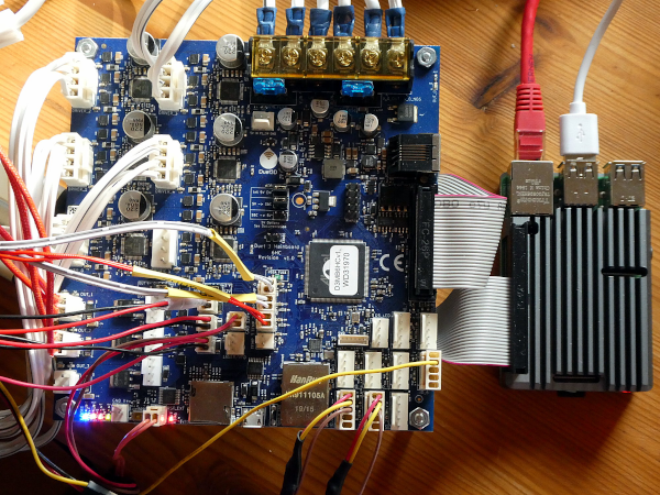](png/duet3_6hc.png)</center><center><small>Click for bigger picture</small></center>
#### Preventing the immediate bed heating
With the following command this can be done:
`M144` sets the bed in standby mode at startup.
<div id=link_3></div>
### config.g
And here the whole config.g file for a Dual Felix TEC 4.1:
; Configuration file for Duet 3 (firmware version 3)
; executed by the firmware on start-up
;
; generated by weigu.lu 2022-02-06

; General preferences
G90                                               ; send absolute coordinates...
M83                                               ; ...but relative extruder moves
M550 P"duet3dual"                                 ; set printer name (must be Raspi host name!)

; Drives
M569 P0.1 S1                                      ; physical drive 0.1 (Y) goes forwards (S1)
M569 P0.2 S1                                      ; physical drive 0.2 (Z) goes forwards
M569 P0.3 S0                                      ; physical drive 0.3 (E0) goes backwards (S0)
M569 P0.4 S0                                      ; physical drive 0.4 (E1) goes backwards
M569 P0.5 S1                                      ; physical drive 0.4 (X) goes forwards
M584 X0.5 Y0.1 Z0.2 E0.3:0.4                      ; set drive mapping
M350 X16 Y16 Z16 E16:16 I1                        ; configure microstepping with interpolation
M92 X76.19 Y76.19 Z1600.00 E164.00:164.00         ; set steps per mm
M566 X600.00 Y600.00 Z18.00 E228.00:228.00        ; set maximum instant. speed changes (mm/min)
M203 X12000.00 Y12000.00 Z600.00 E1800.00:1800.00 ; set maximum speeds (mm/min)
M201 X1100.00 Y1100.00 Z100.00 E10000.00:10000.00 ; set accelerations (mm/s^2)
M906 X1275 Y1275 Z1275 E1275:1275 I20             ; set motor currents (mA) and idle factor (%)
M84 S20                                           ; Set idle timeout

; Axis Limits
M208 X0:240 Y0:205 Z0:200                         ; set axis minima and maxima

; X and Y Endstops
M574 X1 S1 P"io0.in"                              ; configure active-low endstop (X) pin io0.in
M574 Y1 S1 P"io1.in"                              ; configure active-low endstop (Y) pin io1.in

; Z-Probe
M558 P5 C"io6.in" H5 F60 T6000                    ; set Z probe type to unmodulated
                                                  ; and the dive height + speeds
G31 P500 X7 Y35 Z0.5                              ; set Z probe trigger value, offset
                                                  ; and trigger height
M557 X7:240 Y35:200 S20                           ; define mesh grid (use probe values!)
;M671 X110:40:40 Y94:231:-38 P0.5                 ; this is not needed here; look in bed.g

; Heaters
; bed
M308 S2 P"temp2" Y"thermistor" A"S2" T100000 B4092; conf. sensor 2 (S2 bed) thermistor pin temp2
M950 H0 C"out0" T2 Q50                            ; create bed heater out0, PWM freq to 50Hz
                                                  ; and map it to sensor 2 (T2)
M143 H0 S105                                      ; set temperature limit for heater 0 to 105C
M307 H0 B0 R0.461 C354.5 D15.20 S0.75 V18.9       ; B0 = no bang-bang (PID) S0.75 = PWM limit
M140 H0 R20 S55                                   ; map heated bed to heater 0
; left extruder                                   ; conf. sensor 0 (left ext.) thermistor temp0
M308 S0 P"temp0" Y"thermistor" A"S0_Left" T100000 B4092
M950 H1 C"out1" T0 Q250                           ; nozzle heater on out1, PWM freq to 250Hz
                                                  ; and map it to sensor 0 (T0)
M143 H1 S275                                      ; set temperature limit for heater 1 to 275C
M307 H1 B0 R6.834 C86.2 D9.68 S0.75 V19.0         ; B0 = no bang-bang (PID) S0.75 = PWM limit
M570 H1 P5 T30                                    ; raise overshoot limit to 30°C (5s)
; right extruder                                  ; conf. sensor 1 (right ext.) thermistor temp1
M308 S1 P"temp1" Y"thermistor" A"S1_Right" T100000 B4092
M950 H2 C"out2" T1 Q250                           ; nozzle heater on out2, PWM freq to 250Hz
                                                  ;and map it to sensor 1 (T1)
M143 H2 S275                                      ; set temperature limit for heater 2 to 275C
M307 H2 B0 R7.048 C79.2 D9.09 S0.75 V19.0         ; B0 = no bang-bang (PID) S0.75 = PWM limit
M570 H2 P5 T30                                    ; raise overshoot limit to 30°C (5s)


; Fans
M950 F0 C"out7" Q5                                ; create fan 0 print cooling fan out7 pwm 5Hz
M106 P0 C"print-cooling" S0.0                     ; set fan 0 value
M950 F1 C"out8" Q5                                ; create fan 1 pin heatsink out8 and pwm 5Hz
M106 P1 C"heat_sink" S1.0                         ; set fan 1 value

; LEDs
M950 F2 C"out9" Q250                              ; create fan 2 pin out7 and set its frequency
M106 P2 C"Light" S1.0                             ; set fan 2 value

; Tools
M563 P0 D0 H1 F0 S"T0_Ex_Left"                    ; define tool T0 (felix: left ext.) D0=Drive 3
G10 P0 X-12.19 Y0 Z0                              ; set tool 0 axis offsets
G10 P0 R120 S185                                  ; set initial tool 0 active, standby temp. 120C
M563 P1 D1 H2 F0 S"T1_Ex_Right"                   ; define tool T1 (right extruder)
G10 P1 X0 Y0 Z0                                   ; set tool 1 axis offsets
G10 P1 R120 S185                                  ; set initial tool 1 active, standby temp. 120C

; weigu.lu
M144                                              ; switch bed to standby at startup
<div id=link_4></div>

### Homing

After homing I see in DWC X = 23 Z = 5.5. This is explained by the `homeall.g` file (in System). Let's take a look:
; homeall.g
; called to home all axes
;
; generated by RepRapFirmware Configuration Tool v2.1.8 on Thu Apr 23 2020 11:28:28 GMT+0200 (Central European Summer Time)
G91                     ; relative positioning
G1 H2 Z3 F6000          ; lift Z relative to current position
G1 H1 X-245 Y-210 F1800 ; move quickly to X and Y axis endstops and stop there (first pass)
G1 H2 X5 Y5 F6000       ; go back a few mm
G1 H1 X-245 Y-210 F360  ; move slowly to X and Y axis endstops once more (second pass)
G90                     ; absolute positioning
G1 X23 Y-19 F6000       ; go to first bed probe point and home Z
G30                     ; home Z by probing the bed
G29 S1                  ; use the height map

; Uncomment the following lines to lift Z after probing
;G91                    ; relative positioning
;G1 Z3 F100             ; lift Z relative to current position
;G90                    ; absolute positioning
As I want to use the height map I add a `G29 S1` command to `homeall.g`. Look [here](#link_6).

Tip: If things are missing in `homeall.g` to home all axes, the software will try to home those axes by using `homex.g`, `homey.g` or `homez.g`.
; homex.g; called to home the X axis
G91               ; relative positioning
G1 H2 Z5 F6000    ; lift Z relative to current position
G1 H1 X-245 F1800 ; move quickly to X axis endstop and stop there (first pass)
G1 H2 X5 F6000    ; go back a few mm
G1 H1 X-245 F360  ; move slowly to X axis endstop once more (second pass)
G1 H2 Z-5 F6000   ; lower Z again
G90               ; absolute positioning
; homey.g; called to home the Y axis
G91               ; relative positioning
G1 H2 Z5 F6000    ; lift Z relative to current position
G1 H1 Y-210 F1800 ; move quickly to Y axis endstop and stop there (first pass)
G1 H2 Y5 F6000    ; go back a few mm
G1 H1 Y-210 F360  ; move slowly to Y axis endstop once more (second pass)
G1 H2 Z-5 F6000   ; lower Z again
G90               ; absolute positioning
; homez.g ; called to home the Z axis
G91               ; relative positioning
G1 H2 Z3 F6000    ; lift Z relative to current position
G90               ; absolute positioning
G1 X23 Y-19 F6000 ; go to first probe point
G30               ; home Z by probing the bed
<div id=link_5></div>

### Manual Bed Levelling Assistant (MBLA)

With the `G32` code we can perform the bed probing. More infos [here](https://duet3d.dozuki.com/Wiki/Using_the_manual_bed_levelling_assistant).

Our bed has 3 adjusting screws. The Z probe must be correctly defined and calibrated (`M558` and `G31` in config.g).

`G32` uses the file `bed.g`. `M671` in this file defines the X and Y coordinates of the adjusting screws. These coordinates will usually be outside the normal printable area defined by `M208` in `config.g`.
; bed.g
; called to perform automatic bed compensation via G32
;M561                          ; clear any bed transform
;G29                           ; probe the bed and enable compensation
G28                                ; home
M401                               ; deploy Z probe
M671 X148:40:40 Y101:233:-38 P0.5  ; adjusting screws bed middle, front and rear
G30 P0 X148 Y101 Z-99999           ; probe near an adjusting screw middle
G30 P1 X40 Y200 Z-99999            ; probe near an adjusting screw front right
G30 P2 X40 Y35 Z-99999 S3          ; probe near an adjusting screw rear right and report adjustments needed
M402                               ; retract probe
A valid `M671` command enables the bed levelling assistant. When running `G32` to perform bed probing, the final `G30` command (the one with the S parameter) in `bed.g` will cause the assistant to run.

The amount by which each screw should be adjusted is reported. The adjustment requested for the first screw is always zero. The result will be a message like this in console:

```bash
    g32
    Manual corrections required: 0.00 turn up (0.00mm) 0.40 turn up (-0.20mm) 1.13 turn up (-0.57mm)
The second info is front right, the third info back right (Home).
The M3 screws have a standard slope of 0.5 mm. One turn to the left (360°) gives us +0.5 mm. So here we need 0.4*360 = 144° to the left.
| Turn up: | x*360° to the left |
| Turn down: | x*360° to the right |
Using a Mesh Bed Compensation (MBC)
With the G29 code we can perform the bed probing for the mesh bed compensation. More infos here.
The M557 code in config.g defines the grid (see above).
The data is saved on the SD card (.csv file). The Mesh is displayed in Duet Web Control.
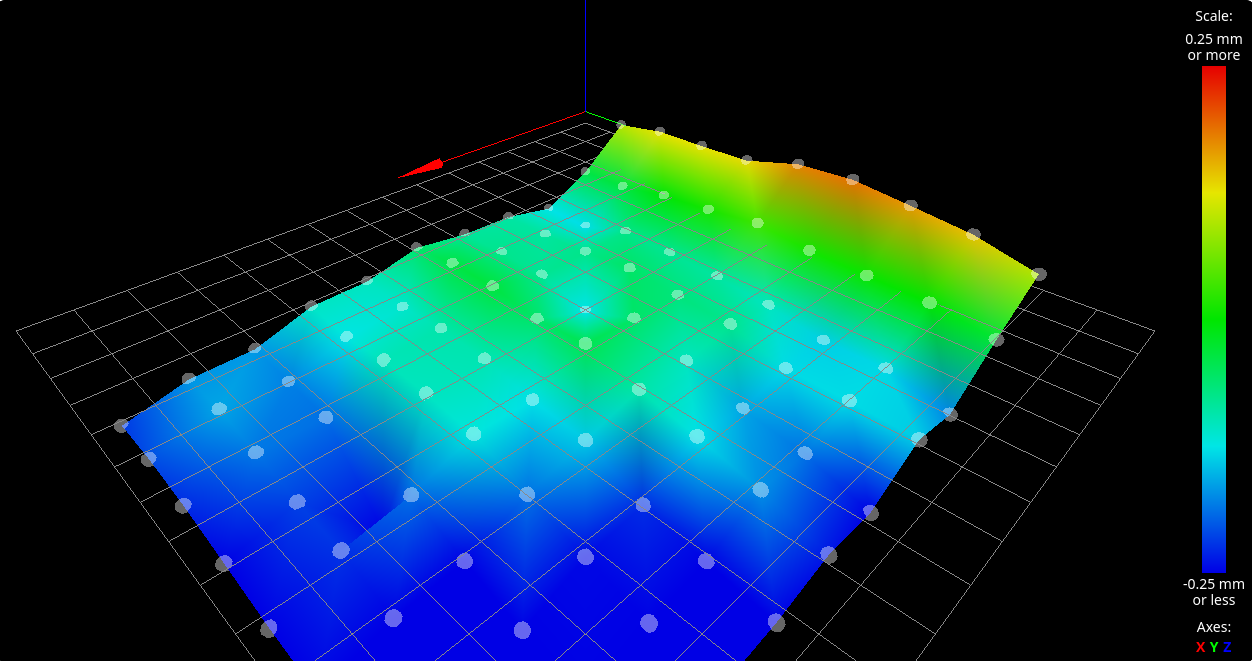
G29 S1 loads the file (in homeall.g). G29 S2 stops using the height map.
With M122 we get a diagnostic report to see if mesh compensation is on. There will be a line that says bed compensation: mesh if it's active.
The bed of my Felix is not really flat as you can see. Mesh bed compensation really helps for big parts.
Pi shutdown
I added a bush-button (Pin 40 (GPIO21) to Ground) to my Raspi. When the button is pressed for less than 3 seconds, my Pi reboots. If pressed for more than 3 seconds it shuts down.
The code is on github.com/gilyes/pi-shutdown. Pay attention, because the code uses the pin numbering (board) and not the GPIO numbering. If you use pin 5 (GPIO3) and it is pressed while shut down, the Pi restarts. This is not possible with pin 40.
If RPi lib is not installed, do this with:
sudo apt install python3-rpi.gpio
I added the following line to /etc/rc.local (before the exit 0!):
python3 /home/pi/pishutdown.py &
Downloads
- Config files and STL files on github: https://github.com/weigu1/felix_goes_duet3
Interesting links
- https://github.com/Duet3D
- https://docs.duet3d.com/User_manual/Overview/Getting_started_Duet_3_MB6HC
- https://docs.duet3d.com/User_manual/Machine_configuration/SBC_setup
- https://docs.duet3d.com/How_to_guides/Wiring_your_Duet_3
- https://docs.duet3d.com/User_manual/Connecting_hardware/IO_E_stop
- https://docs.duet3d.com/User_manual/RepRapFirmware/RepRapFirmware_overview
- https://docs.duet3d.com/User_manual/Connecting_hardware/Z_probe_connecting
- https://docs.duet3d.com/User_manual/Tuning/scanning_z_probe_calibration
- https://docs.duet3d.com/User_manual/Connecting_hardware/Heaters_tuning
- https://docs.duet3d.com/User_manual/Reference/Duet_Web_Control_Manual
- https://docs.duet3d.com/User_manual/RepRapFirmware/RepRapFirmware_overview
- https://github.com/Duet3D/RepRapFirmware/releases
- https://reprap.org/wiki/List_of_Firmware
- https://github.com/MarlinFirmware/Configurations/archive/release-2.0.6.zip
- https://dyzedesign.com/2019/04/differences-12v-24v-3d-printer/
- https://reprap.org/wiki/Thermistor
